


AXIS 225FD - Unit Connectors
36
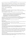
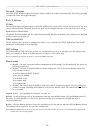
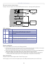
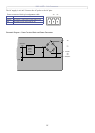
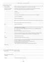
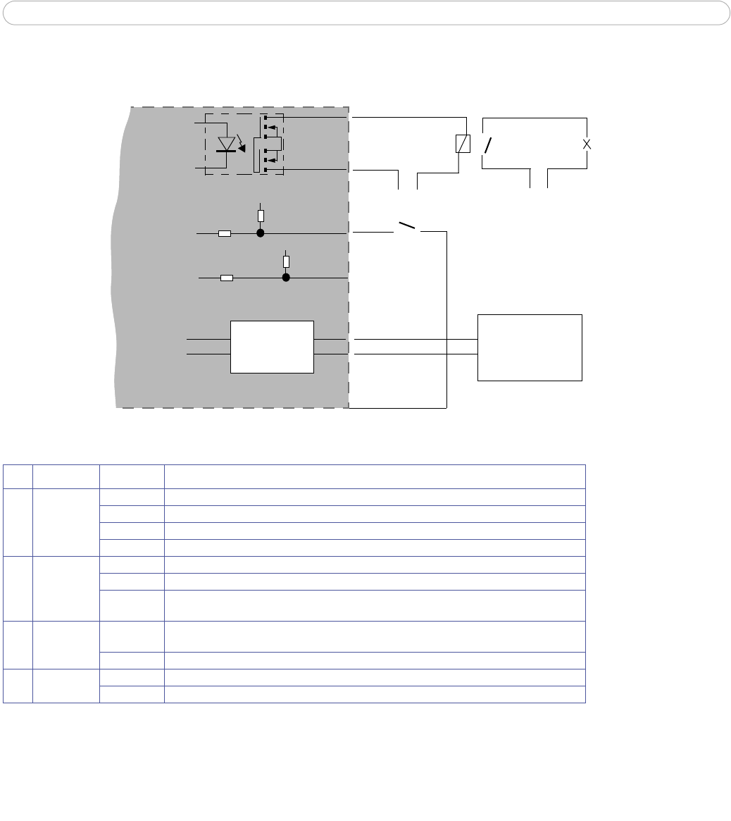
I/O terminal connector schematic diagram
Example schematic diagram of the AXIS 225FD terminal connector - showing possible applications.
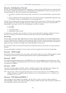
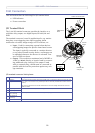
LED indicators:
Power connections
Power can be supplied to the camera by the following methods:
• PoE (Power over Ethernet) via the network cable.
This will automatically be detected if available via the network.
Note that PoE only provides power for the camera and the fan (not the heater).
• Connect the supplied indoor power adapter to the power
connector block in the camera casing. Note that this
indoor power adapter only provides power for the camera and the fan (not the heater).
• Connect
an outdoor power supply to the power connector block in the camera casing. For information on
available outdoor power supplies, please visit the Support pages at http://www.axis.com/techsup/
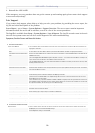
Power Connector Block
The power connector block supports both
AC and DC input power.
The DC supply is 9-24V. Connect the negative pole to the
GND pin and the positive pole to the DC+ pin.
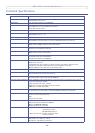
LED Function Color Description
1
Network Green Steady for connection to 100 Mbit/s network. Flashes for network activity.
Amber Steady for connection to 1
0 Mbit/s network. Flashes for network activity.
Red Flashes rapid red, together with the Status indicator,
for hardware error.
Unlit No connection.
2
Status Green Shows steady green for normal operation.
Amber Shows steady amber during reset to factory
default or when restoring settings.
Red Slow flash for failed upgrade. Rapid flash, toget
her with the Network indicator, for hardware
error.
3
Heater Green Shows steady green if the connected power supply can deliver the correct voltage for the
heater (See Power, on page 42 of Technical Specifications ).
Red Incorrect voltage for the heater (i.e., the volt
age is either too high or too low).
4
Power Green Normal operation.
Amber Flashes green/amber during firmware upgrade.
o
o
o
o
A
B
3
4
5
External Device
o
o
1
2
RS-485/422
Mains Power
24V DC
Appliance
Optional
Relay
Switch
o
o
o
o
o
o
o
o
o
7 GND
Switch, etc.
6
+3.3V
+3.3V