


AXIS 225FD - Product Features
6
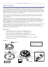
Power connector block - for connection of a power supply. See Power connections, on page 36.
I/O terminal connector - The
I/O terminal connector provides the physical interface to one solid state relay
output, two digital inputs, RS-485/422 and GND. For more information, see Unit Connectors,
on page 35.
Network connector - The
AXIS 225FD connects to the network via a standard network cable, and automatically
detects the speed of the local network segment (10BaseT/100BaseTX Ethernet). This socket can also be used to
power the AXIS 225FD via PoE (Power over Ethernet). The camera also negotiates the correct power level when
using PoE.
Serial Number - This number
is used during installation.
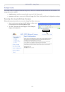
Control Button - This button is
used during the installation using the AXIS Internet Dynamic DNS Service (see
the Installation Guide) or to restore the factory default settings, as described in Advanced, on p
age 33.
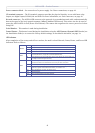
LED Indicators
After completion of the startup and self test
routines, the multi-colored Network, Status, Heater, and Power LED
indicators flash as follows:
Network
Green Steady for connection to 100 Mbit/s network. Flashes for network activity.
Amber Steady for connection to 1
0 Mbit/s network. Flashes for network activity.
Red Flashes rapid red, together with the S
tatus indicator, for hardware error.
Unlit No connection.
Heater
Green Shows steady green if the connected power supply
can deliver the correct voltage for
the heater (See Power, on page
42 of Technical Specifications).
Red Shows steady red if the connected power supply
cannot deliver the correct voltage (i.e.,
the voltage is either too high or too low).
Status
Green Shows steady green for normal operation. Can be c
onfigured to flash green at intervals
whenever the camera is accessed. See the online help for more information.
Amber Shows steady amber during reset to factory
default or when restoring settings.
Red Slow flash for failed upgrade (see
Emergency Recovery Procedure, on page 38).
Rapid flash, together with the Network indicator,
for hardware error.
Unlit When configured for “no flash” on camera access.
Power
Green Normal operation.
Amber Flashes green/amber during firmware upgrade.