


42
AXIS Q1755/-E - Unit connectors
• Digital input - An alarm input for connecting devices that can toggle between an open and closed circuit, for exam-
ple: PIRs, door/window contacts, glass break detectors, etc. When a signal is received the state changes and the input
becomes active (shown under Events > Port Status.)
Notes:
•
The I/O connector on AXIS Q1755-E is connected to the housing electronics at delivery and will trigger an input port
event to indicate a fan or heater error when activated. See
Events,
on page 25, for information on how to set up an
event.
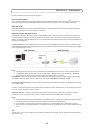
• For information on how to connect external devices, refer to the Installation Guide supplied with the product.
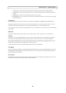
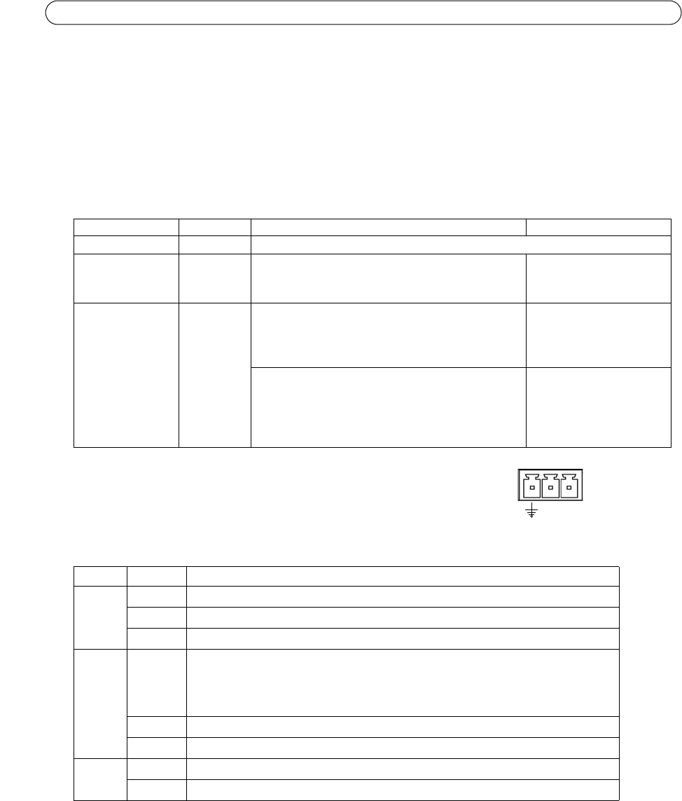
Power connector - 3-pin terminal block 8-20 VDC or 20-24 VAC.
LED indicators
Note:
Please refer to the product’s Installation Guide for information on the LED indicators for the housing electronics
(fan/heater).
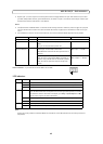
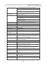
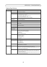
Function Pin number Notes Specifications
GND
1 Ground
3.3V DC Power 2 Can be used to power auxiliary equipment.
Note:
This pin can only be used as power out.
Max load = 250mA
Configurable
(Input or Output)
3 - 4 Digital input - Connect to GND to activate, or leave
floating (or unconnected) to deactivate.
AXIS Q1755-E: Connected to housing electronics at
delivery.
Min input = - 40V DC
Max input = + 40V DC
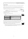
Digital output - Uses an open-drain NFET transistor
with the source connected to GND. If used with an
external relay, a diode must be connected in parallel
with the load, for protection against voltage tran-
sients.
Max load = 100mA
Max voltage = + 40V DC
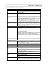
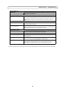
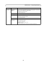
LED Color Indication
Network Green Steady for connection to a 100 Mbit/s network. Flashes for network activity.
Amber Steady for connection to 10 Mbit/s netw
ork. Flashes for network activity.
Unlit No network connection.
Status Green Steady green for normal operation.
Note: The Status LED can be configured to be
unlit during normal operation, or to flash
only when the camera is accessed. To configure, go to Setup > System Options > LED.
See the online help files for more information.
Amber Steady during startup, during reset to fact
ory default or when restoring settings.
Red Slow flash for failed upgrade.
Power Green Normal operation.
Amber Flashes green/amber during firmware upgrade.
+
~
~