


AXIS P3367–VE Fixed Dome Network Camera
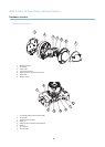
Hardware overview
Connectors
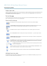
Network connector - RJ-45 Ethernet connector. Supports Power over Ethernet (PoE). A shielded network cable (STP) must be
used to protect the product against power surges.
Audio in (pink) - 3.5 mm input for a mono microphone, or a line-in mono signal (left channel is used from a stereo signal).
Audio out (green) - 3.5 mm output for audio (line level) that can be connected to a public address (PA) system or an active s peaker
with a built-in a mplifier. A stereo connector must be used for the audio out.
SD card slot - A standard or high-capacity SD card (not included) can be used for local recording with removable storage. For
instructions on how to insert and remove an SD card, please refer to the Installation Guide.
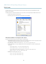
Note
Before removal, the SD card should be unmounted to prevent corruption of recordings. To unmount the SD card, go to Setup
>SystemOptions>Storage>SDCardand click Unmount.
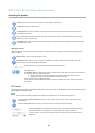
Control button - The control button is used for:
• ConnectingtoanAXISVideoHostingSystemservice.Seepage 37. To connect, press and hold the button for about 1
second until the Status LED flashes green.
• Connecting to AXIS Internet Dynamic DNS Service. See page 37. To connect, press and h old the button for about 3
seconds.
• Resetting the product to factory default setting s. See page 43.
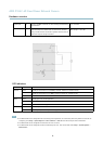
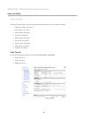
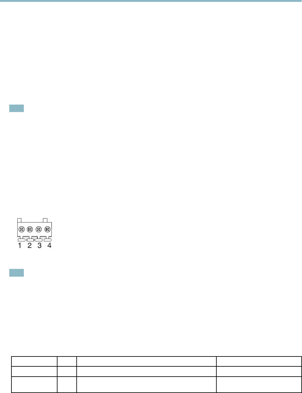
I/O connector
Note
For technical specifications, see page 50.
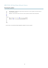
I/O terminal connector - Use in a pplications for e.g . motion detection, event triggering, time lapse recording and alarm notifications.
In addition to an auxiliary power and a GND pin, the I/O terminal connector pro v ides the interface to:
• Digital output — For connecting external devices such as relays and LEDs. Connected devices can be activated by the
VAPIX® Application Programming Interface, output buttons on the Live View page or by an A ction Rule. The output will
show as active (shown under System Opti
ons > Ports & Devices) if the alarm device is activated .
• Digital input — An alarm input for c
onnecting devices that can toggle between an open and closed circuit, for example:
PIRs, door/window contacts, glass break detectors, etc. When a signal is received the state changes and the input
becomes active (shown under System Options > Ports & Devices).
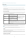
Function Pin Notes
Specifications
GND
1
Ground
3.3 V DC Power
2
Can be used t o p
ower auxili ary equipment.
Note: This pin can only be used as power out.
Max load = 50 mA
5