


LTC 9385 Series | Instruction Manual | Installation
EN
|
12
Bosch Security Systems | January 26, 2005
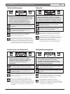
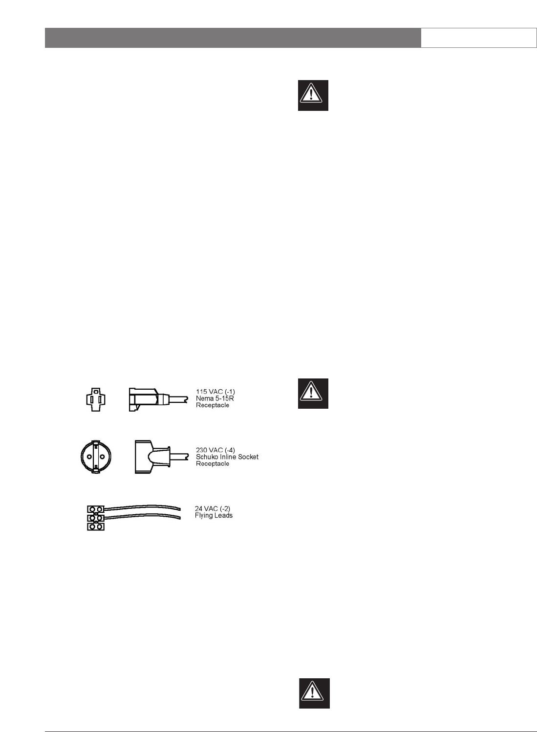
LTC 9385/20 Housings
These housings are to be connected to 24VAC, and
are designed for use where site power is 24volts. The
LTC 9385/20 housings should only be used with
24volt cameras. The integral heater/defogger requires
24volts. The housing is shipped with the heater/
defogger connected to the terminal block.
Installing a 24 volt camera into the LTC 9385/20
housing simply requires the two flying leads be attached
to the camera's terminal block. See FIGURE 10.
LTC 9385/50 Housings
These housings are to be connected to 230VAC, and
are designed for use where site power is 230volts. The
LTC 9385/50 housings should only be used with
230volt cameras. The integral heater/defogger requires
230volts. The housing is shipped with the
heater/defogger connected to the terminal block.
Installing a 230 volt camera into the LTC 9385/50
housing simply requires the camera's line cord to be
plugged into the Schuko inline receptacle provided.
See FIGURE 10.
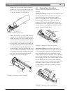
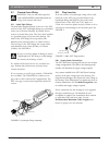
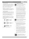
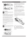
FIGURE 10 Camera Connections
5.9 Video Coax Connection
WARNING: Only use the cables specified
under INSTALLATION, Cable Requirements for
wiring of the video coax connection.
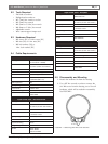
If lens control or feed-through wires will be used:
1. Install the long flexible portion of the small
liquid-tight fitting on the video coax cable and
pull the cable through the small fitting on the
rear end of the base assembly. The fitting will
accept cables with diameters from 4.6mm
(0.181in.) to 7.9mm (0.312in.). See FIGURE 11.
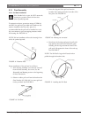
2. Attach a BNC connector to the coax and connect
it to the camera. Pull any excess cable through
the liquid-tight fitting and tighten the flex fitting
to 4.0N-m to 4.5N-m (35in. lb to 40in. lb). This
torque rating is approximately 1 to 1 1/2 turns
past the point that the fitting starts to grip the
cable. Failure to do so will result in water
damage to all electronic parts. Use a tie wrap
(included) to provide strain relief on the video
cable at the exit point (inside the unit).
Be sure to securely tighten all fittings to ensure
a liquid-tight seal. Not doing so could damage
the camera, the housing, or both.
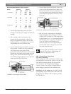
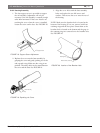
If no lens control or feed-through wires will be used:
1. Install the long flexible portion of a large
liquid-tight fitting on the video coax cable and
pull the cable through the large right fitting on
the rear end of the base assembly. Refer to
FIGURES 11 and 12.
2. Attach a BNC connector to the coax and
connect it to the camera. Pull any excess cable
through the liquid tight fitting and tighten the
flex fitting to 8.5N-m to 9.0N-m (75in. lb to
80in. lb). This torque rating is approximately
1 to 1 1/2 turns past the point that the fitting
starts to grip the wire. Failure to do so will
result in water damage to all electronic parts.
Use a tie wrap (included) to provide strain relief
on the video cable at the exit point (inside the
unit).
Be sure to securely tighten all fittings to
ensure a liquid-tight seal. Not doing so could
damage the camera, the housing, or both.