


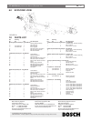
LTC 9385 Series | Instruction Manual | Installation
EN
|
13
Bosch Security Systems | January 26, 2005
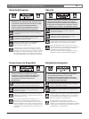
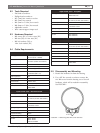
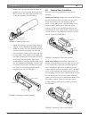
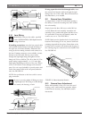
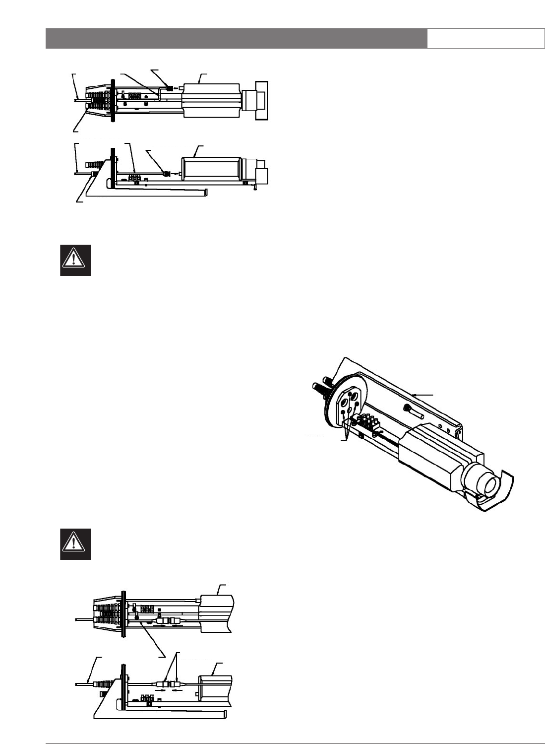
FIGURE 11 Video Coax Connection
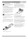
5.10 Lens Wiring
WARNING: Only use the cables specified
under INSTALLATION, Cable Requirements for
wiring of the lens.
If installing a zoom lens, insert the lens control cable
with installed flexible fitting in through the fitting on
the right rear of the base assembly. Attach the lens
wiring to the lens mating connector and connect it to
the lens. If mating connector is not available, connect
directly to the lens cable. Pull any excess cable
through the liquid-tight fitting and tighten the flex
fitting to 8.5N-m to 9.0N-m (75in. lb to 80in. lb). This
torque rating is approximately 1 to 1 1/2 turns past
finger-tight, depending on the size of the wire. Failure
to do so will result in water damage to all electronic
parts. Use a tie wrap (included) to provide strain relief
on the lens control cable at the exit point (inside the
unit). See FIGURE 12.
NOTE: See specification on the lens cord for correct
plug connection.
Be sure to securely tighten all fittings to ensure
a liquid-tight seal. Not doing so could damage
the camera, the housing, or both.
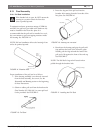
FIGURE 12 Lens Control Cable Wiring
If using a pan/tilt with a feed-through cable, insert
the camera/lens function cable in through the right
fitting at the rear of the cradle. Wire the functions as
described above, or as needed.
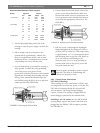
5.11 Camera/Lens Orientation
A unique feature of the LTC 9385 Series housing is
the ability to rotate the mounting base 360
º around
the rail assembly.
Simply loosen the three M4 screws with a M3 hex
wrench. Rotate the base assembly around the rail
assembly to any position and tighten the M4 screws.
It is preferable to keep the rail assembly under the
camera, not over it. See FIGURE 13.
NOTE: Make sure the breather hole is located at the
bottom of the housing. If it is not, remove both front
retaining rings and the face plate. Orient them so the
breather hole is located at the bottom and the gaps in
the retaining rings are centered over the breather hole.
See FIGURE 20.
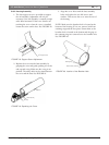
FIGURE 13 Base Assembly Rotation
5.12 Camera/Lens Adjustment
Before final assembly of the cover over the rest of
housing, verify camera and lens operation. Adjust
camera/lens as necessary. See individual camera
instructions.
M4 Screws
Base Assembly
CCD Camera
CCD Camera
Video Coax Cable
BNC Connector
BNC Connector
Video Coax Cable
Small Fitting
Small Fitting
CCD Camera
CCD Camera
Lens Control Connectors
Lens Control Cable