


LTC 9385 Series | Instruction Manual | Installation
EN
|
15
Bosch Security Systems | January 26, 2005
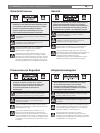
5.13.2 Housing Assembly
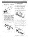
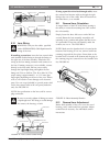
1. The lens support screw is provided to support
the rail assembly. Adjustment will only be
necessary if the rail assembly is rotated at angle
other than horizontal. If the screw head is not
touching the cover when the cover is installed,
loosen the screw until it does. See FIGURE 18.
FIGURE 18 Support Screw Adjustment
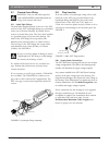
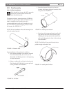
2. Replace the cover onto the base assembly by
grasping the cover and gently pushing it over the
end cap and o-ring. Make sure the o-ring is not
pinched. The safety cable can be routed between
the cover and the base. See FIGURE 19.
FIGURE 19 Replacing the Cover
3. Align the cover holes with the base assembly
holes and replace the two M4 screws and
washers. This secures the cover onto the rest of
the housing.
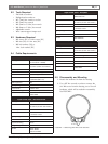
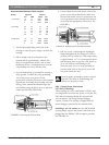
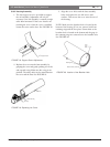
NOTE: Make sure the breather hole is located at the
bottom of the housing. If it is not, remove both front
retaining rings and the face plate. Orient them so the
breather hole is located at the bottom and the gaps in
the retaining rings are centered over the breather hole.
See FIGURE 20.
FIGURE 20 Location of the Breather Hole
Breather Hole (centered)
Retaining Ring
Front
Face
Plate
Lens Support Screw
Base Assembly
End Cap
Cover