


LTC 9385 Series | Instruction Manual | Installation
EN
|
9
Bosch Security Systems | January 26, 2005
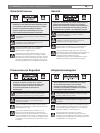
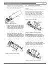
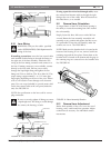
3. Remove the cover from the base assembly by
grasping the cover and gently pulling forward.
Do not remove the safety cable from the cover
or the base assembly. See FIGURE 2.
FIGURE 2 Removing the Cover
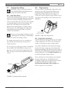
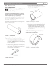
4. Attach the housing to an appropriate mount or
pan/tilt. Use the instructions provided with the
mount or pan/tilt. The base assembly has three
clearance holes for mounting. Use three M6
screws and nuts or three 1/4in. screws and nuts
(not provided). Lock washers are required (not
provided). Rotating the rail assembly will allow
access to the mounting holes. This can be
accomplished by loosening the three M4 screws.
See also Camera/Lens Orientation. It will be easier
to mount the base before installing the camera,
but it may be mounted anytime during the
installation process. See FIGURE 3.
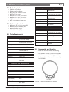
FIGURE 3 Mounting the Base Assembly
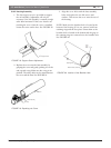
5.6 Camera/Lens Installation
Place the camera/lens combination onto the rail
assembly.
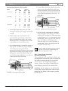
Fixed Lens Cameras: Position the camera/lens so that
the lens is positioned over the heater but not past it.
Secure the camera to the rail assembly with the
1/4-20 x 3/8in. BHC screw, a nylon bushing, and a
0.4mm (0.016in.) plastic spacer. Place the nylon
bushing over the screw and slide both between the
rails through the front cut-out section. Slide the spacer
over the screw so it is positioned in-between the rails
and the camera. See FIGURE 4.
FIGURE 4 Mounting a Fixed Lens Camera
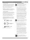
Zoom Lens Cameras: Position the camera/lens so
that the lens is positioned over the heater but not past
it. The camera/lens combination will determine the
screws and spacers that will be needed. Secure the
camera and lens to the rail assembly with 1/4-20 BHC
screws, nylon bushings, and plastic spacers. Place the
nylon bushings over the screws and slide both between
the rails through the front cut-out section. Slide the
spacer over the screw so it is positioned in-between the
rails and the camera. There are four large spacers
(3.2mm) and four small spacers (0.4mm) provided.
See FIGURE 5.
FIGURE 5 Mounting a Zoom Lens Camera
Camera
Bushing
Spacer
Spacer
Screw
Rails
Mounting Holes
M4 Screws
Rail Assembly
Base Assembly
Cover