


FlexiDome2X IP Camera Installation | en 33
Bosch Security Systems Installation and Operation Manual AR18-10-B006 | v1.1 | 2010.06
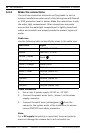
Network (and PoE) connection
1. Use an unshielded twisted pair (UTP) or shielded twisted
pair (STP) Category 5e cable, maximum length 100 meters.
2. Use the RJ45 female-to-female network cable connector to
connect the network cable of the system to the RJ45
connector of the camera (Auto MDIX compliant).
By default, power is supplied to the camera via the Ethernet
cable, compliant with the Power-over-Ethernet standard.
Note:
The RJ45 female-to-female network cable connector supplied
with the camera is unshielded and is appropriate for all
applications that use unshielded twisted pair (UTP) network
cable (most types). For applications that use shielded twisted
pair (STP) connection cable and need to meet the EMC Alarm
immunity standard (EN50130-4) or the EMC Railway imunity
standard (EN50121-4), a shielded RJ45 female-to-female
network cable connector (not supplied) shall be used.
Alarm input/output
Use the alarm input to connect external alarm devices such as
door contacts or sensors. A zero potential make-contact or
switch can be used as the actuator (use a bounce-free contact
system).
Alarm input: TTL logic +5 V nominal; 40 VDC maximum; DC
coupled with 22 kOhm pull-up to +3.3 V.
Alarm output: Maximum voltage 30 VAC or 40 VDC; maximum
0.5 A continuous, 10 VA. Use the alarm relay output for
switching external devices such as lamps or sirens.
1. Refer to the cable tree table to identify the wire colors for
connecting the alarm input and output.
2. In the menu system, configure the alarm input as active
low or active high.
3. In the menu system, configure the relay output to operate
as either normally open (NO) or normally closed (NC).