


7-13
Cisco PIX Security Appliance Hardware Installation Guide
78-15170-03
Chapter 7 PIX 535
Installing a Memory Upgrade
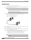
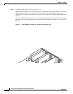
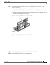
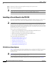
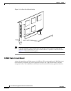
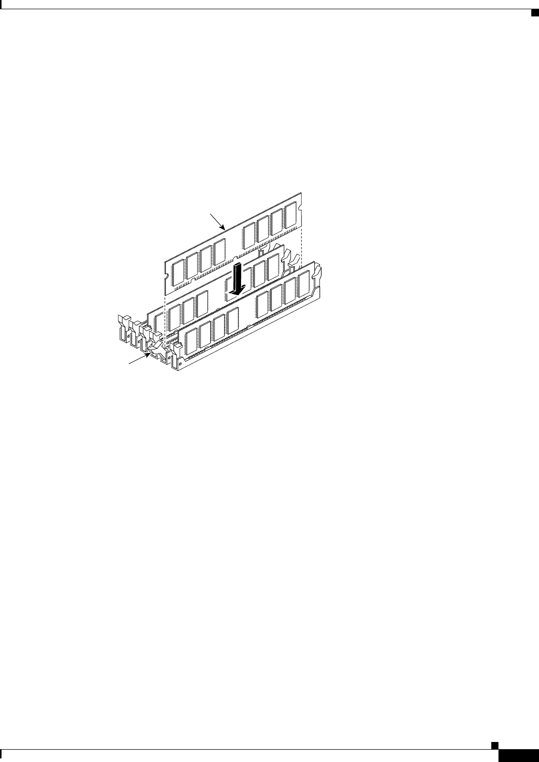
Step 8 Install the first DIMM strip in socket J41 and the second DIMM strip in socket J44, as shown in
Figure 7-8 and Figure 7-9.
a. Carefully grasp the DIMM strip from either end, being careful not to touch the components on the
strip. Note that the DIMM strip is notched, which prevents it from being installed incorrectly. So,
do not force installation.
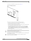
b. Open the two plastic wing connectors at the sides of the memory socket, insert the DIMM strip, and
close the wing connectors to secure it in place.
Figure 7-8 Inserting a DIMM Memory Strip in the PIX 535
Figure 7-9 Securing a DIMM Memory Strip in the PIX 535
Step 9
Reinstall the component tray and the screws that hold the assembly in place.
Step 10 Remove the grounding wrist-strap.
Step 11 Rack-mount the chassis or place it on a flat, stable surface.
89067
J40
J41
J42
J43
J44
J45
DIMM
Wing
connector