


7-4
Cisco PIX Security Appliance Hardware Installation Guide
78-15170-03
Chapter 7 PIX535
PIX 535 Product Overview
PIX 535 Network Interface Description
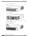
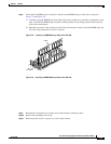
There are three separate buses for the nine interface slots in the PIX 535. The interfaces are counted from
right to left on the PIX 535.
The slots and buses are configured as follows:
• Slots 0 and 1-64-bit/66 MHz Bus 0
• Slots 2 and 3-64-bit/66 MHz Bus 1
• Slots 4 to 8-32-bit/33 MHz Bus 2
For optimum performance and throughput for the interface circuit boards, use the following guidelines:
• A total of two 10/100 Fast Ethernet interfaces, and support for up to twelve additional 10/100 Fast
Ethernet or nine Gigabit Ethernet interfaces are configurable with the unrestricted license.
• For best performance, the PIX-1GE-66 (66 MHz) circuit boards should be installed in a 64bit/66
MHz card slot, before they are installed in a 32-bit/33 MHz card slot. You can install up to nine
PIX-1GE-66 circuit boards in the PIX 535. If it is necessary to install PIX-1GE-66 circuit boards in
a 32-bit/33 MHz card slot, it would be best to use these for interfaces with lower throughput
requirements.
• If Stateful Failover is enabled for PIX-1GE-66 traffic, the failover link must be PIX-1GE-66. The
amount of Stateful Failover information is proportional to the amount of traffic flowing through the
PIX security appliance and if not configured properly, loss of state information or 256-byte block
depletion can occur.
• The PIX-1FE circuit board (33 MHz) can be installed in any bus or slot (32-bit/33 MHz or 64-bit/66
MHz). Up to nine PIX-1FE circuit boards, or up to two PIX-4FE, circuit boards can be installed.
The PIX-1FE circuit boards should be installed in the 32-bit/33 MHz card slots first.
• The PIX-4FE card can only be installed in a 32-bit/33 MHz card slot and must never be installed in
a 64-bit/66 MHz card slot. Installation of this circuit board in a 64-bit/66 MHz card slot can cause
the system to hang at boot time.
• The PIX-4FE-66 may be installed in any slot. If there is a shortage of 64-bit/66 MHz card slots (the
slots are being used for 1GE-66 or PIX-VACPLUS), the PIX-4FE-66 should be installed in 32-bit/33
MHz card slot.
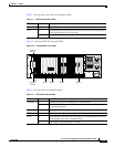
Note On the PIX-4FE card, port 0 is on the top and port 3 is on the bottom.
• Do not mix the PIX-1FE circuit boards with the PIX-1GE-66 circuit boards on the same 64-bit/66
MHz bus (Bus 0 or Bus 1). The overall speed of the bus is reduced by the lower speed circuit board.
• The PIX-1GE circuit board is not recommended for use in the PIX 535, as it can severely degrade
performance. It is only capable of half the throughput of the PIX-1GE-66 circuit board. If this circuit
board is detected in the PIX 535, a warning about degraded performance will be issued.
• The VPN Accelerator (PIX-VPN-ACCEL) can only be installed in a 32-bit/33 MHz card slot.
• The VPN Accelerator Card+ (PIX-VACPLUS) should always be installed in a 64-bit/66 MHz card
slot. VPN performance will be degraded by roughly a factor of 4 if this recommendation is not
followed.
For more information on the number of interfaces for each of the PIX Firewall models, click here.