


7-17
Cisco PIX Security Appliance Hardware Installation Guide
78-15170-03
Chapter 7 PIX 535
Installing a Circuit Board in the PIX535
Installing a Circuit Board
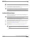
Note It is not necessary to remove the chassis cover on the PIX 535 to install or replace a circuit board. A
component tray, that slides out from the rear panel, contains slots for installing circuit boards and
memory boards.
To install a circuit board in the PIX 535, perform the following steps:
Step 1 Locate the grounding strap from the accessory kit. Fasten the grounding strap to your wrist so that it
contacts your bare skin. Attach the other end to bare metal on the PIX 535 chassis.
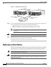
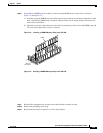
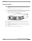
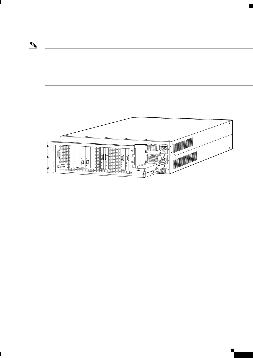
Figure 7-11 The Component Tray at the Back of the PIX 535
Step 2
Loosen the attachment screws from the rear panel of the component tray and slide the tray out.
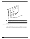
Step 3 Select a slot for the circuit board and remove the screw and slot cover plate from the back panel on the
component tray.
Step 4 Install the circuit board into the slot. The front plate on the circuit board should be against the slot
opening on the component tray back panel.
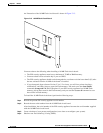
Step 5 Use the screw that was removed in Step 3 to attach the circuit board front plate to the component tray
rear panel.
Step 6 Reinstall the component tray and tighten the attachment screws.
61917
S
T
A
T
U
S
S
T
A
T
U
S