


7-21
Cisco PIX Security Appliance Hardware Installation Guide
78-15170-03
Chapter 7 PIX 535
Installing the PIX 535 DC Model
Note You must use a GE failover link when connecting the PIX 535 with GE interfaces.
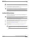
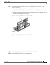
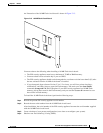
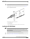
The Gigabit Ethernet circuit board and the fiber optic cable connection are shown in Figure 7-15.
Figure 7-15 Gigabit Ethernet Circuit Board
The Gigabit Ethernet circuit board has three LEDs:
• TX—Transmitting data
• RX—Receiving data
• LINK—The Gigabit Ethernet circuit board has established a network connection
Installing the PIX 535 DC Model
Warning
Before performing any of the following procedures, ensure that power is removed from the DC circuit.
To ensure that all power is OFF, locate the circuit breaker on the panel board that services the DC
circuit, switch the circuit breaker to the OFF position, and tape the switch handle of the circuit
breaker in the OFF position.
To install the PIX 535 DC power model, perform the following steps:
Step 1 Remove the blank cover plate, if a blank cover plate is installed on the PIX 535.
Step 2 Read the Regulatory Compliance and Safety Information document for your respective software version.
33010
TX
RX
LINK