


1-4
Cisco Video Surveillance 6400 IP Camera Installation Guide
OL-28494-01
Chapter 1 Overview
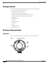
IP Camera Physical Details
General Purpose I/O Terminal Block
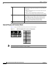
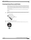
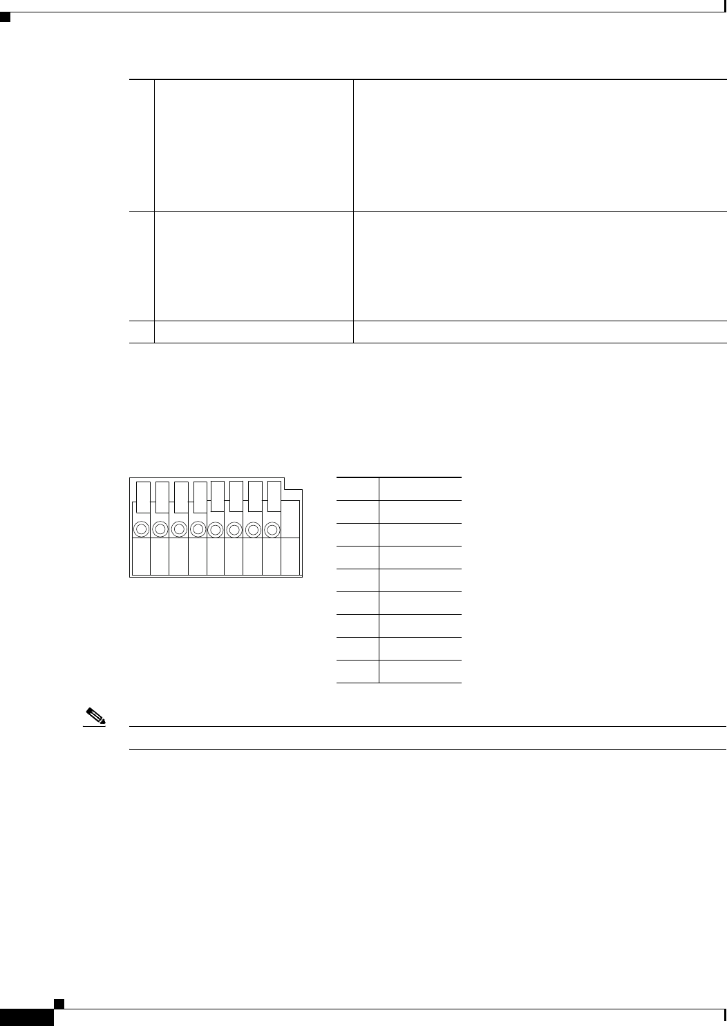
Figure 1-3 shows the GPIO terminal block pin locations and descriptions.
Figure 1-3 GPIO Terminal Block Pin Locations and Descriptions
Note The maximum output load from pins 7 and 8 is 400mA.
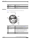
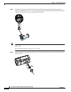
5 Reset button Reboots the IP camera or resets it to a default state. Depending
on how long you depress the reset button, you can do either of
the following:
• Reset—Press and release the reset button. Wait for the IP
Camera to reboot.
• Restore—Press and hold the reset button for about
30
seconds. All settings will be restored to factory default.
6 Audio/Video out (green) Allows the connection of an optional Y cable or mini cable with
BNC connector. You can connect a video monitor to the mini
cable with BNC connector. Both cables are included in the
optional audio/video cables accessory kit can be purchased
from Cisco (Cisco part number CIVS-AVCABLE).
Note Support for audio will be in future releases.
7 Microphone In (pink) Connection for an external microphone.
Pin Description
1 12 VDC-
2 12 VDC+
3 24 VAC
4 24 VAC
5 DI-
6 DI+
7 DO-
8 DO+
87654321