


2-7
Cisco Video Surveillance 6400 IP Camera Installation Guide
OL-28494-01
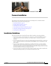
Chapter 2 Camera Installation
Connecting External Power and I/O Cables
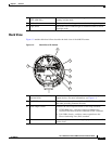
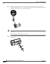
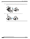
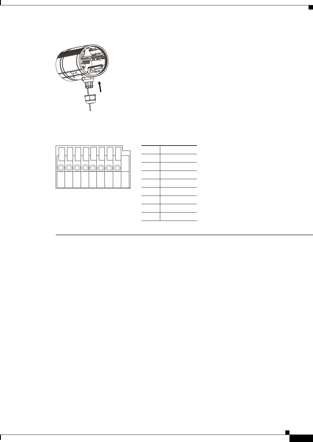
Step 6 Secure the sealing nut (E) tightly.
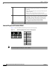
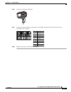
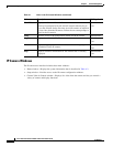
Step 7 Connect the external power and I/O cables to the GPIO terminal block. The pin locations and
descriptions are as follows:
Step 8 Replace the back cover back onto the camera.
Pin Description
112 VDC-
212 VDC+
324 VAC
424 VAC
5DI-
6DI+
7DO-
8DO+
(E)
87654321