


2-6
Cisco Video Surveillance 6400 IP Camera Installation Guide
OL-28494-01
Chapter 2 Camera Installation
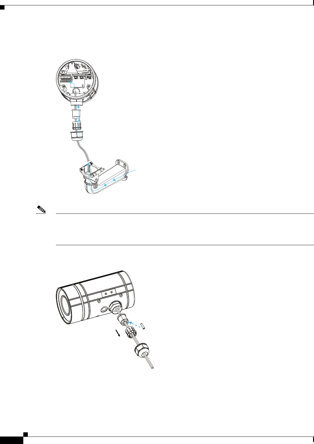
Connecting External Power and I/O Cables
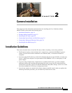
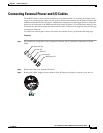
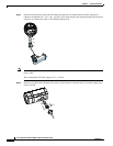
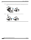
Step 4 Feed the external power cable and I/O cables through the wall mount bracket and the waterproof
connector components (E –> D –> B –> A). Be sure to feed enough cable length through the waterproof
connector to connect the cables to the GPIO terminal block.
Note There are seven holes on the seal (B), and the widest hole with a crack on the side is specific for the
power cable.
The recommended I/O cable gauge is 2.0 ~ 2.8 mm.
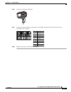
Step 5 Push the seal (B) into the housing (D), and to avoid moisture, insert the seals (C) into the empty holes
on the seal (B).
4
(D)
(B)
(A)
(E)
(E)
(C)
(B)
(D)