


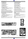
Servicehinweise / Service Instructions GV44…, GV45…, GV46…
1 - 62 GRUNDIG Service-Technik
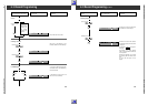
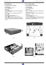
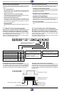
2. Ausbauhinweise
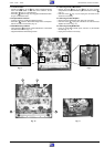
2.1 Bedieneinheit I ausbauen
– Rastnasen
G
lösen (Fig. 5).
– Bedieneinheit I abnehmen.
– Gegebenenfalls Steckverbindung lösen.
2.1.1 Bedieneinheit II ausbauen
– Rastnase
H
lösen (Fig. 5).
– Bedieneinheit II abnehmen.
– Gegebenenfalls Steckverbindung lösen.
2.2 Netzteilbaustein ausbauen
– Schraube
K
(Fig. 6) herausdrehen.
– Rastnasen
L
ausrasten sowie Führungsleiste
L
vorsichtig in
Pfeilrichtung drücken und Netzteilbaustein herausnehmen (Fig. 6).
– Gegebenenfalls Steckverbindungen lösen.
2.2.1 Reparaturen im Netzteil
Bei Reparaturen des Netzteilbausteins – Trenntrafo benutzen!
Sollen Bauteile im nicht netzgetrennten Teil des Netzteils ausge-
tauscht werden, müssen Sie den Abschirmdeckel abnehmen.
Nach der Reparatur darauf achten, daß der Abschirmdeckel des
Netzteilbausteins angebracht ist! Des weiteren muß der Netzteil-
baustein nach dem Einbau mit der Schraube
K
befestigt sein.
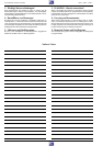
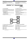
2.3 Chassisplatte ausbauen
– Netzteilbaustein ausbauen.
– Arretierung
M
entfernen (Fig. 7b).
– Rastnasen
O
(Fig. 7b) nach unten drücken, Chassisplatte in
Pfeilrichtung (Fig. 7a) schieben und herausnehmen.
– Gegebenenfalls Steckverbindungen lösen.
Nach dem Einbau der Chassisplatte darauf achten, daß die
Arretierung
M
angebracht ist!
Hinweis: Die Chassisplatte wird ohne EPROM (IC7055) ausgeliefert.
Nach Austausch: Abgleichschritte gemäß Kapitel 3 durchführen.
2. Disassembly Instructions
2.1 Removing the Keyboard Unit I
– Release the locking lugs
G
(Fig. 5).
– Withdraw the Keyboard Unit I.
– Unplug the connector if necessary.
2.1.1 Removing the Keyboard Unit II
– Release the locking lug
H
(Fig. 5).
– Withdraw the Keyboard Unit II.
– Unplug the connector if necessary.
2.2 Removing the Power Supply Board
– Undo the screw
K
(Fig. 6).
– Release the locking lugs
L
, push the guide
L
carefully in the
direction of the arrow and take out the Power Supply Board (Fig. 6).
– Unplug the connectors if necessary.
2.2.1 Repairs on the Power Supply Board
Use an isolating transformer when repairing the Power Supply Unit!
For replacement of components in the non-isolated circuits of the
Power Supply Unit remove the shielding cover.
On completion of the repairs take care that the shielding cover is
refitted to the Power Supply Unit! Do not forget to fasten it with
screw
K
.
2.3 Removing the Family Board
– Remove the Power Supply Board.
– Remove lock
M
(Fig. 7b).
– Press the locking lugs
O
(Fig. 7b) downwards, push the Family
Board in the direction of the arrow (Fig. 7a) and remove it.
– Unplug the connectors if necessary.
After replacement of the Family Board do not forget to refit the
lock
M
!
Advice: The Family Board is delivered without the EPROM (IC7055).
After replacement: Alignments according to chapter 3.
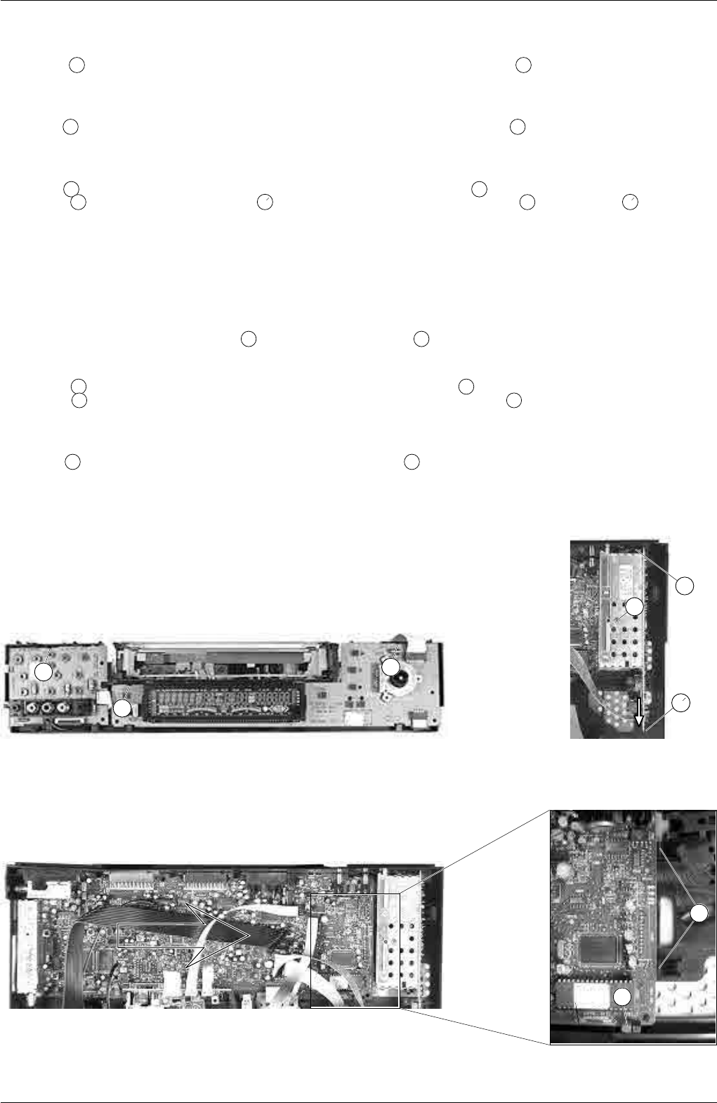
O
M
Fig. 5 Fig. 6
Fig. 7a Fig. 7b
K
G
G
H
L
L