


22 EN
VIDEO PLAYBACK
(cont.)
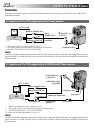
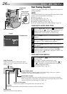
Connections
These are some basic types of connections. When making the connections, refer also to your VCR and TV
instruction manuals.
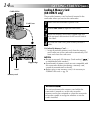
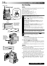
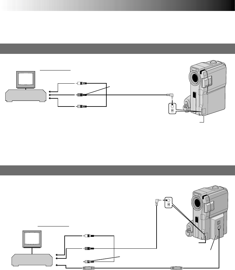
A. Connection to a TV or VCR equipped only with A/V input connectors
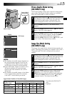
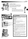
B. Connection to a TV or VCR equipped with an S-VIDEO IN and A/V input connectors
White to AUDIO L IN**
To S-VIDEO IN
Red to AUDIO R IN**
Yellow: Not connected
To S-VIDEO
S-Video cable
(optional)
Audio/Video cable
(provided)
TV
* When connecting the cables, open this cover.
** The Audio cable is not required for watching still images only.
***AV IN/OUT:GR-DVM75, AV OUT:GR-DVM55
To TV or VCR
* When connecting the cables, open this cover.
** The Audio cable is not required for watching still images only.
*** AV IN/OUT:GR-DVM75, AV OUT:GR-DVM55
**** Refer to “Jack Box Attachment” (੬ pg. 23).
NOTE:
In order to maintain optimum performance of the camcorder, provided cables may be equipped with one or
more core filter. If a cable has only one core filter, the end that is closest to the filter should be connected to
the camcorder.
Jack box****
To AV IN/OUT***
or AV OUT***
Connector cover*
VCR
NOTE:
In order to maintain optimum performance of the camcorder, provided cables may be equipped with one or
more core filter. If a cable has only one core filter, the end that is closest to the filter should be connected to
the camcorder.
TV
Yellow to VIDEO IN
Audio/Video cable
(provided)
Red to
AUDIO R IN**
White to AUDIO L IN**
To
AV IN/OUT*** or
AV OUT***
Connector cover*
To TV or VCR
VCR