


70 EN
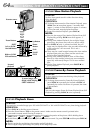
DISPLAY
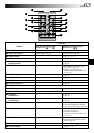
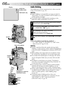
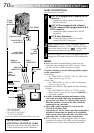
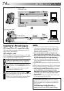
MAKE CONNECTIONS
Also refer to pg. 22 and 23.
1
A JVC VCR equipped with a Remote PAUSE
connector . . .
... connect the editing cable to the Remote
PAUSE connector.
A JVC VCR not equipped with a Remote
PAUSE connector but equipped with an R.A.
EDIT connector . . .
... connect the editing cable to the R.A.EDIT
connector.
A VCR other than above . . .
... connect the editing cable to the remote
control’s PAUSE IN connector.
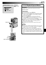
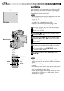
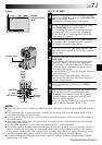
2
Insert a recorded tape into the camcorder. Set the
VIDEO/DSC Switch to “VIDEO” (GR-DVM75 only),
then set the Power Switch to “ ” while pressing
down the Lock Button located on the switch.
3
Turn the VCR power on, insert a recordable tape and
engage the AUX mode (refer to the VCR’s instructions).
NOTES:
●
Before Random Assemble Editing, make sure the
indications do not appear on the TV monitor. If they
do, they will be recorded onto the new tape.
To choose whether or not the following displays appear
on the connected TV . . .
•Date/Time
.... set “DATE/TIME” to “AUTO”, “ON” or “OFF” in the
Menu Screen (੬ pg. 42, 43).
•Time Code
.... set “TIME CODE” to “ON” or “OFF” in the Menu
Screen (੬
pg. 42, 43).
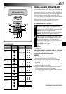
•Playback Sound Mode, Tape Speed And Tape Running
Displays
.... set “ON SCREEN” to “LCD” or “LCD/TV” in the
Menu Screen (੬ pg. 42, 43). Or, press DISPLAY on
the remote control.
●
In order to maintain optimum performance of the
camcorder, provided cables may be equipped with
one or more core filter. If a cable has only one core
filter, the end that is closest to the filter should be
connected to the camcorder.
●
The S-Video cable is optional. Be sure to use the
YTU94146A S-Video cable.
Consult the JVC Service Center described on the sheet
included in the package for details on its availability.
Make sure to connect the end with a core filter to the
camcorder. The core filter reduces interference.
●
When editing on a VCR equipped with a DV input
connector, an optional DV cable can be connected
instead of an S-Video cable and audio/video cable.
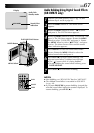
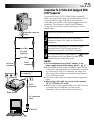
To Remote
PAUSE or
R.A.EDIT
VCR
TV
To PAUSE IN
Editing
cable
(provided)
S-Video
cable
(optional)
Audio/Video
cable (provided)
* EDIT: GR-DVM75
JLIP: GR-DVM55
** AV IN/OUT: GR-DVM75
AV OUT: GR-DVM55
***Connect when an S-Video cable is not used.
To JLIP*
or EDIT*
To S-VIDEO
For GR-DVM55 Owners:
ATTENTION FOR EDITING CABLE
Make sure you connect the plug which has
3 rings around the pin to the camcorder.
To
S-VIDEO
IN
USING THE REMOTE CONTROL UNIT
(cont.)
To AV IN/OUT**
or AV OUT**
Yellow to
VIDEO IN***
White to
AUDIO L IN
Red to
AUDIO R IN
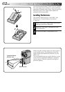
Open the cover.