


EN87
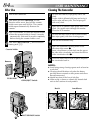
Controls
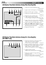
1 E-MAIL CLIP REC Button
(GR-DVM75 only)................................੬ pg. 61
2 D. SOUND PLAY Button
(GR-DVM75 only)................................੬ pg. 56
3 •MENU Wheel [+, –, PUSH] ...............੬ pg. 38
•LCD Monitor Brightness
Control [+, –] ....................................੬ pg. 18
4 •Power Zoom Lever [T/W] ..................੬ pg. 19
•Speaker Volume Control
[VOL.] ...............................................੬ pg. 21
5 Power Switch
[ , , , OFF] ............................੬ pg. 16
6 Lock Button .........................................੬ pg. 16
7 Recording Start/Stop Button .................੬ pg. 18
8 Snapshot Button
[SNAPSHOT] ...............੬ pg. 26, 27, 50, 59, 60
9 •FOCUS Button ..................................੬ pg. 51
•BLANK Button...................................੬ pg. 24
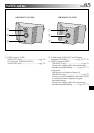
0 Battery Release Switch
[BATT. RELEASE] ....................................੬ pg. 8
! OPEN/EJECT Switch .............................੬ pg. 12
@ SELECT Button (GR-DVM75 only) ... ੬ pg. 30, 32
# JUMP Button (GR-DVM75 only) ..........੬ pg. 30
$ INDEX Button
(GR-DVM75 only)..........................੬ pg. 30, 56
% •Play/Pause Button [4/6] ..................੬ pg. 21
•NIGHT-ALIVE Button.........................੬ pg. 45
^ •Fast-Forward Button [3] ...............੬ pg. 21
•PROGRAM AE Button .......................੬ pg. 46
& •Stop Button [5] .................................੬ pg. 21
•BACKLIGHT Button...........................੬ pg. 52
* •Rewind Button [2] .......................੬ pg. 21
•EXPOSURE Button.............................੬ pg. 52
( VIDEO/DSC Switch [VIDEO, ]
(GR-DVM75 only)................................੬ pg. 16
) CARD OPEN Switch
(GR-DVM75 only)................................੬ pg. 14
q Diopter Adjustment Control .................੬ pg. 10
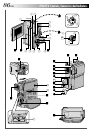
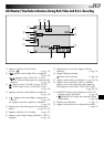
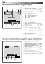
Connectors
The connectors to are located beneath a cover.
Digital Video Connector
[DV IN/OUT] (i.link*) ..............੬ pg. 58, 74, 75
* i.Link refers to the IEEE1394-1995 industry
specification and extensions thereof. The logo
is used for products compliant with the i.Link
standard.
•Audio/Video Input (GR-DVM75 only)/
Output Connector
[AV IN/OUT or AV OUT] ......੬ pg. 22, 57, 70
•Headphone Connector [ ]
(GR-DVM75 only) .............................੬ pg. 66
DC Input Connector [DC IN] .............੬ pg. 8, 9
Indicators
Tally Lamp .....................................੬ pg. 18, 40
Power Lamp...................................੬ pg. 16, 18
CHARGE Lamp ......................................੬ pg. 8
Other Parts
LCD Monitor..................................੬ pg. 18, 19
Battery Pack/Jack Box Mount ...........੬ pg. 8, 23
Speaker................................................੬ pg. 21
Camera Sensor
Be careful not to cover this area, a sensor
necessary for shooting is built-in here.
Stereo Microphone ..............................੬ pg. 66
Flash (GR-DVM75 only).......................੬ pg. 54
Flash Sensor (GR-DVM75 only)
Be careful not to cover this area, as it contains a
sensor required by the flash.
Lens
Lens Protector
When using an optional lens filter (commercially
available), you must first detach the lens
protector.
Remote Sensor .....................................੬ pg. 62
Grip Strap ............................................੬ pg. 10
Viewfinder ...........................................੬ pg. 10
Viewfinder Cleaning Hatch ..................੬ pg. 84
Memory Card Cover
(GR-DVM75 only)................................੬ pg. 14
Cassette Holder Cover .........................੬ pg. 12
Tripod Mounting Socket .......................੬ pg. 10