


EN23
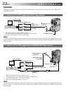
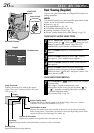
NOTES:
●
It is recommended to use the AC Adapter as the
power supply instead of the battery pack
(
੬
pg. 9).
●
The S-Video cable is optional. Be sure to use the
YTU94146A S-Video cable.
Consult the JVC Service Center described on the
sheet included in the package for details on its
availability. Make sure to connect the end with a
core filter to the camcorder. The core filter
reduces interference.
●
To monitor the picture and sound from the
camcorder without inserting a tape or memory
card*, set the camcorder’s Power Switch to “ ”
or “ ”, then set your TV to the appropriate input
mode.
*GR-DVM75 only
●
Make sure you adjust the TV sound volume to its
minimum level to avoid a sudden burst of sound
when the camcorder is turned on.
●
If you have a TV or speakers that are not specially
shielded, do not place the speakers adjacent to
the TV as interference will occur in the camcorder
playback picture.
●
While the Audio/Video cable is connected to the
AV connector, sound cannot be heard from the
speaker.
●
If no image is displayed or no sound is heard from
the TV, set “S/AV INPUT” to “OFF” in the Menu
Screen (GR-DVM75 only,
੬
pg. 42).
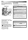
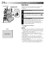
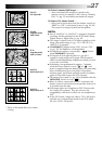
1
Make sure all units are turned off.
2
Connect the camcorder to a TV or VCR as
shown in the illustration (੬ pg. 22).
If using a VCR . . . go to step 3.
If not . . . go to step 4.
3
Connect the VCR output to the TV input,
referring to your VCR’s instruction manual.
4
Turn on the camcorder, the VCR and the TV.
5
Set the VCR to its AUX input mode, and set the
TV to its VIDEO mode.
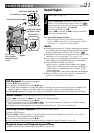
To choose whether or not the following displays
appear on the connected TV . . .
•Date/Time
.... set “DATE/TIME” to “AUTO”, “ON” or “OFF”
in the Menu Screen (੬ pg. 42, 43).
•Time Code
.... set “TIME CODE” to “ON” or “OFF” in the
Menu Screen (੬
pg. 42, 43).
•Playback Sound Mode, Tape Speed And Tape
Running Displays for video playback
Or
Type of file, Directory/File Names and Image
Number/Total Number of Images for D.S.C.
Playback (GR-DVM75 only)
.... set “ON SCREEN” to “LCD” or “LCD/TV” in
the Menu Screen (੬ pg. 42, 43).
Or, press DISPLAY on the remote control.
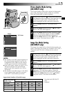
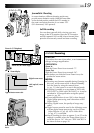
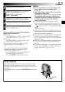
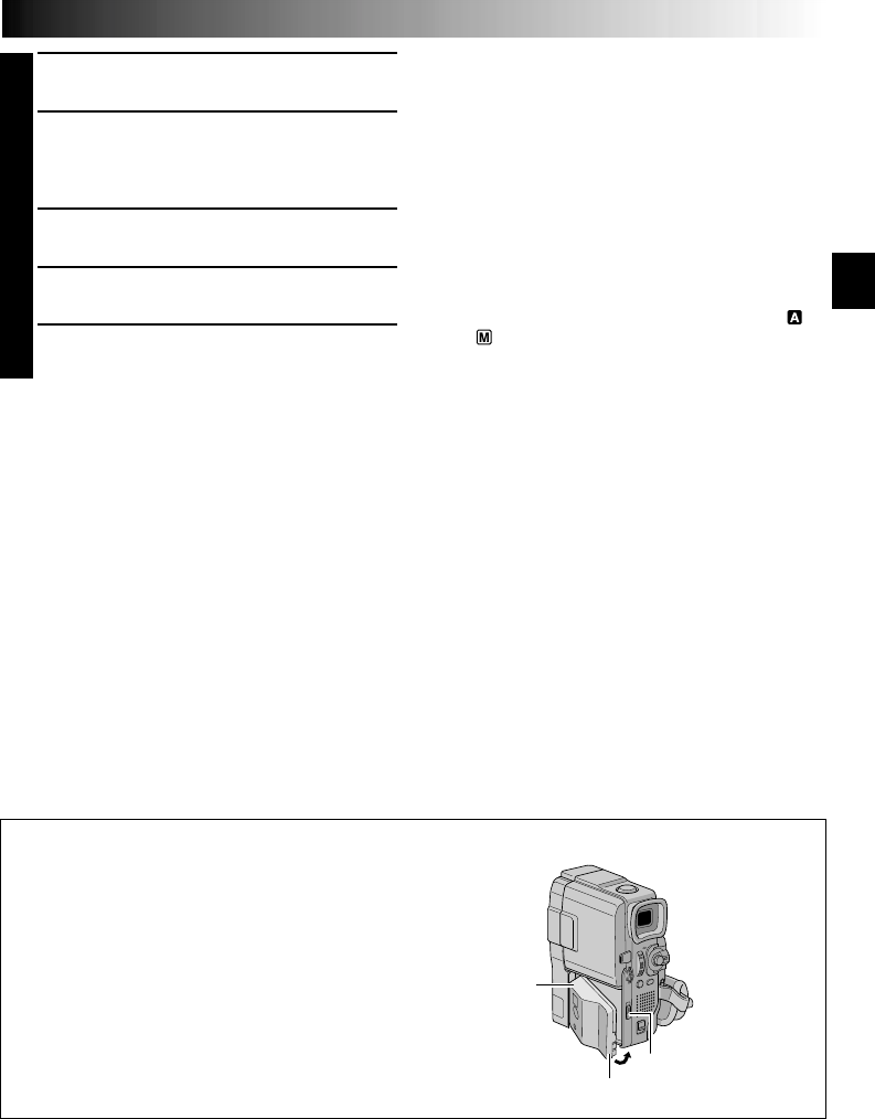
Jack Box Attachment
Insert the terminal end 1 of the jack box into the jack box
mount, then firmly push the end 2 of the jack box in the
direction of the arrow until it locks into place as shown in the
illustration.
To detach the jack box, slide the BATT. RELEASE Switch and
detach it.
1
2
BATT. RELEASE
Switch