


EN
83
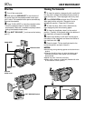
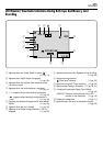
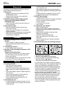
Controls
1 Snapshot Button
[SNAPSHOT] ............................. ੬ pg. 20, 21, 61
2 • Power Zoom Lever [T/W] ..................... ੬ pg. 22
•Speaker/Headphone Volume Control
[VOLUME] ........................................... ੬ pg. 25
3 Power Switch [ , , , OFF]....... ੬ pg. 14
4 Recording Start/Stop Button.................. ੬ pg. 18
5 Lock Button............................................ ੬ pg. 14
6 Dioptre Adjustment Control ................... ੬ pg. 10
7 • Stop Button [5].................................... ੬ pg. 25
•Programme AE Button [PROG.AE] ..... ੬ pg. 38
8 • Rewind Button [
2
] ............................. ੬ pg. 25
•NIGHT Button ...................................... ੬ pg. 38
9 • Play/Pause Button [
4
/6] ..................... ੬ pg. 25
•BACKLIGHT Button ............................. ੬ pg. 40
0 • Fast-Forward Button [
3
].................... ੬ pg. 25
•FADE/WIPE Button.............................. ੬ pg. 36
! VIDEO/MEMORY Switch
[VIDEO, MEMORY]................................ ੬ pg. 14
@ TITLE Button ......................................... ੬ pg. 48
# INDEX Button ............................ ੬ pg. 27, 45, 48
$ • NAVI Button ......................................... ੬ pg. 42
•SELECT Button ..................... ੬ pg. 26, 49 – 53
% •E-MAIL Button ..................................... ੬ pg. 46
•INFO Button......................................... ੬ pg. 27
^ D. SOUND Button .................................. ੬ pg. 45
& Monitor Open Button [PUSH OPEN] ..... ੬ pg. 18
* FOCUS Button....................................... ੬ pg. 24
( EXPOSURE Button ............................... ੬ pg. 40
) •MENU Wheel [▲, ▼, PUSH]................ ੬ pg. 28
•LCD Monitor Brightness Control.......... ੬ pg. 18
q Manual Focus Ring ................................ ੬ pg. 24
w Battery Release Switch
[BATT. RELEASE] .................................... ੬ pg. 9
e OPEN/EJECT Switch ............................ ੬ pg. 12
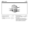
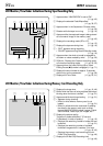
Connectors
The connectors r to y are located beneath a cover.
r Headphone Connector [PHONE]........... ੬ pg. 72
No sound is output from the speaker when
headphones are connected to this connector.
t PRINTER Connector
Connect to the optional printer equipped with a
PRINT DATA connector. Refer to the separate
“FOR OWNERS OF AN OPTIONAL PRINTER”
instruction sheet.
y Audio/Video Input/Output Connector
[AV] ............................................ ੬ pg. 54, 59, 67
To connect a cable to the connector u, open the LCD
monitor.
u Digital Video Connector
[DV IN/OUT] (i.Link*) ................. ੬ pg. 56, 58, 60
*i.Link refers to the IEEE1394-1995 industry
specification and extensions thereof. The logo
is used for products compliant with the i.Link
standard.
i Multi Connector
When attaching the Jack Box to the camcorder,
this part is connected.
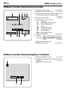
Indicators
o Power Lamp ........................................... ੬ pg. 18
p Tally Lamp ............................................. ੬ pg. 18
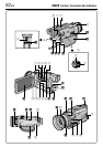
Other Parts
Q Speaker ................................................. ੬ pg. 42
W Grip Strap .............................................. ੬ pg. 10
E Shoulder Strap Eyelets .......................... ੬ pg. 10
R Viewfinder Cleaning Hatch .................... ੬ pg. 80
T Battery Pack Mount ................................. ੬ pg. 9
Y LCD Monitor .................................... ੬ pg. 18, 19
U Lens Hood ............................................... ੬ pg. 6
I Info-Shoe
Attach the optional video light/flash/zoom
microphone.
O Camera Sensor
Be careful not to cover this area, a sensor
necessary for shooting is built-in here.
P Viewfinder .............................................. ੬ pg. 10
a Remote Sensor...................................... ੬ pg. 62
s Stereo Microphone ................................ ੬ pg. 72
d Stud Hole ............................................... ੬ pg. 10
f Tripod Mounting Socket ......................... ੬ pg. 10
g MEMORY CARD Cover ......................... ੬ pg. 13