


22 EN
Master Page: Left-Heading0
VIDEO PLAYBACK (cont.)
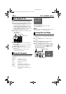
These are some basic types of connections. When
making the connections, refer also to your VCR and
TV instruction manuals.
* Not required for watching still images only.
** Connect when your TV/VCR has only A/V input
connectors.
*** Connect when your TV/VCR has S-VIDEO IN
and A/V input connectors. In this case, it is not
necessary to connect the yellow video cable.
**** When connecting the cable, open the cover.
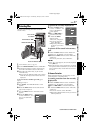
1 Make sure all units are turned off.
2 Connect the camcorder to a TV or VCR as shown
in the illustration.
If using a VCR, go to step 3.
If not, go to step 4.
3 Connect the VCR output to the TV input,
referring to your VCR’s instruction manual.
4 Turn on the camcorder, the VCR and the TV.
5 Set the VCR to its AUX input mode, and set the
TV to its VIDEO mode.
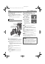
To choose whether or not the following displays
appear on the connected TV…
● Date/Time
Set “DATE/TIME” to “AUTO”, “ON” or “OFF”.
(੬ pg. 31, 41)
Or, press DISPLAY on the remote control to turn
on/off the date indication.
● Time Code
Set “TIME CODE” to “ON” or “OFF”.
(੬ pg. 31, 41)
● Indications other than date/time and time code
Set “ON SCREEN” to “OFF”, “LCD” or “LCD/TV”.
(੬ pg. 31, 41)
NOTES:
● It is recommended to use the AC Adapter as the
power supply instead of the battery pack.
(੬ pg. 11)
● The S-Video cable is optional. Be sure to use the
YTU94146B S-Video cable. Consult the JVC
Service Center described on the sheet included in
the package for details on its availability. Make
sure to connect the end with a core filter to the
camcorder. The core filter reduces interference.
● To monitor the picture and sound from the
camcorder without inserting a tape or memory
card, set the camcorder’s Power Switch to “A” or
“M”, then set your TV to the appropriate input
mode.
● Make sure you adjust the TV sound volume to its
minimum level to avoid a sudden burst of sound
when the camcorder is turned on.
● If you have a TV or speakers that are not specially
shielded, do not place the speakers adjacent to the
TV as interference will occur in the camcorder
playback picture.
● When a cable is connected to the AV or
headphone connector, sound cannot be heard
from the speaker.
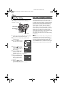
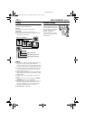
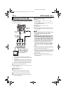
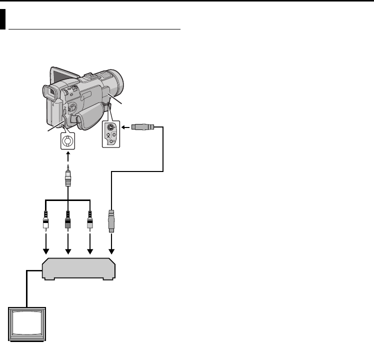
Connections To A TV Or VCR
TV
VCR
Connector
Cover****
Connector
Cover****
A
A White to AUDIO L IN*
B Red to AUDIO R IN*
C Yellow to VIDEO IN**
D To S-VIDEO IN***
BCD
Audio/Video
cable
(provided)
To AV
To S
S-Video cable
(optional)
GR-DV801US.book Page 22 Wednesday, January 22, 2003 5:39 PM