


EN 81
Master Page: Right
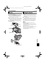
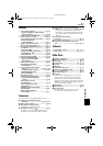
Controls
a •Menu Wheel [MENU]........................ ੬ pg. 31
•Speaker/Headphone Volume Control
[MENU/VOLUME +, –] ..................... ੬ pg. 20
b Snapshot Button [SNAPSHOT]....... ੬ pg. 23, 42
c Power Zoom Lever [T/W] .................... ੬ pg. 18
d •Focus Adjustment Button [FOCUS] ... ੬ pg. 45
•Blank Search Button
[BLANK SEARCH] ............................. ੬ pg. 21
e Diopter Adjustment Control................ ੬ pg. 12
f Recording Start/Stop Button................ ੬ pg. 17
g Power Switch [A, M, PLAY, OFF] ........ ੬ pg. 13
h Lock Button ......................................... ੬ pg. 13
i •Stop Button [8]................................. ੬ pg. 20
•Program AE Button [PROG.AE] ......... ੬ pg. 33
j •Rewind Button [
3
].......................... ੬ pg. 20
•NIGHT Button................................... ੬ pg. 42
k Play/Pause Button [4/9] .................... ੬ pg. 20
l •Fast-Forward Button [
5
] .................੬ pg. 20
•Wipe or Fader Effect Button
[FADE/WIPE]..................................... ੬ pg. 32
m Index Button [INDEX].......................... ੬ pg. 26
n Thumbnail Storing Button
[NAVI STORE]...................................... ੬ pg. 49
o •D.S.C. Playback Select Button
[SELECT].................................... ੬ pg. 24 – 29
•Navigation Button [NAVI] ................. ੬ pg. 48
p VIDEO/MEMORY Switch
[VIDEO/MEMORY].............................. ੬ pg. 13
q Title Button [TITLE].............................. ੬ pg. 44
r •Information Button [INFO]................ ੬ pg. 26
•E-Mail Clip Recording Button
[E-MAIL]............................................ ੬ pg. 50
s Battery Release Switch
[BATT.RELEASE]................................... ੬ pg. 10
t Cassette Open/Eject Switch
[OPEN/EJECT]...................................... ੬ pg. 15
u Backlight Compensation Button
[BACK LIGHT]..................................... ੬ pg. 47
v Monitor Opening Button
[PUSH OPEN]...................................... ੬ pg. 17
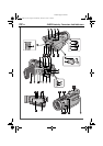
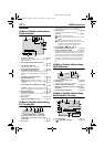
Connectors
The connectors are located beneath the covers.
W S-Video Input/Output Connector
[S-VIDEO]................................ ੬ pg. 22, 52, 62
X Edit Connector [EDIT] ........................ ੬ pg. 62
Y Microphone connector [MIC]
Attach the optional microphone.
Z Headphone Connector [ ] ................ ੬ pg. 59
No sound is output from the speaker when
headphones are connected to this connector.
a Digital Video Connector [DV IN/OUT]
(i.Link*) ....................................੬ pg. 53, 54, 66
* i.Link refers to the IEEE1394-1995 industry
specification and extensions thereof. The logo
is used for products compliant with the i.Link
standard.
b USB (Universal Serial Bus)
Connector ............................................੬ pg. 66
c DC Input Connector [DC]..............੬ pg. 10, 11
d Audio/Video Input/Output Connector
[AV]..........................................੬ pg. 22, 52, 62
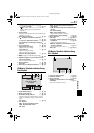
Indicators
I Power/Charge Lamp.......................੬ pg. 13, 17
J Tally Lamp......................................੬ pg. 17, 37
Other Parts
h Shoulder Strap Eyelet .............................੬ pg. 6
i Battery Pack Mount..............................੬ pg. 10
j Grip Strap.............................................੬ pg. 12
k LCD Monitor..................................੬ pg. 12, 18
l Speaker ................................................੬ pg. 20
m Stud Hole
n Tripod Mounting Socket .......................੬ pg. 12
o Card Cover [MEMORY CARD] ............੬ pg. 16
p Cassette Holder Cover..........................੬ pg. 15
q Stereo Microphone...............................੬ pg. 59
r Info-Shoe
Attach only the optional JVC VL-V3U Video
Light, VL-F3U Flash, MZ-V3U Stereo Zoom
Microphone or MZ-V5U Stereo Microphone.
Make sure to turn off the power of the camcorder
and the video light, flash or microphone before
attaching and removing them.
s Viewfinder............................................੬ pg. 12
t Remote Sensor .....................................੬ pg. 56
u Camera Sensor
Be careful not to cover this area, a sensor
necessary for shooting is built-in here.
REFERENCES
GR-DV801US.book Page 81 Wednesday, January 22, 2003 5:39 PM