


E-48
6. Others (continued)
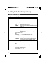
ON
OFF
1234
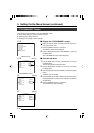
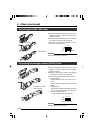
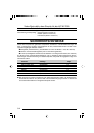
● Attach the supplied clamp filter as shown in the
diagram on the left to reduce unwanted electro-
magnetic emission.
● Attach the clamp filter as shown in the diagram
on the left to this unit as near as possible.
● Set Switch 1 and Switch 4 located at the side of
this unit to [ON] (upper side).
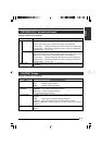
To [DV] Terminal
Connecting the IEEE 1394 Cable
Caution
Perform these when the unit is off.
Switch 1
Wind Once
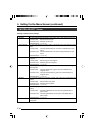
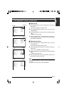
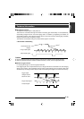
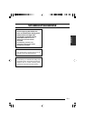
● Attach the supplied clamp filter as shown in the
diagram on the left to reduce unwanted electro-
magnetic emission.
● Attach the clamp filter as shown in the diagram
on the left to this unit as near as possible.
● Set the switches located at the side of this unit.
• Setting Switch 2
Set this switch to [ON] (upper side) for Y/C
output.
Set this switch to [OFF] (lower side) for RGB
output.
• Setting Switch 3
Set this switch to [ON] (upper side) if sync signal
is to be superimposed onto the Green (G)
channel of the video signal.
☞ Page 10 ‘9 Function Setting Switch’
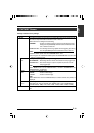
Connecting the analogue output (D-SUB) Cable
Caution
Perform these when the unit is off.
To [RGB, Y/C, SYNC
OUT] Terminal
ON
OFF
1234
Switch 3Switch 2
Switch 4