


E8
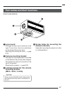
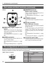
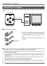
[Rear] ᕧ [REMOTE] terminal
(Metal 10-pin, female)
Used to connect external devices such as
a trigger switch or flash unit.
Pin configurations of connectors ( ੬ page
E9)
ᕨ [POWER] indicator
Lights when power is supplied to the cam-
era.
ᕩ [DC IN] connector
(Mini DIN 8-pin, female)
Power (DC 12V) for the camera is supplied
through this inlet.
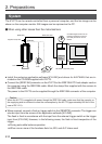
For the power supply, use the AA-P700 AC
adapter. (For medical use, this camera
should be powerd from AA-P700 decid-
edly.)
Pin configurations of connectors ( ੬ page
E9)
Connecting the AC adapter ( ੬ page E16)
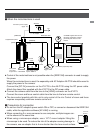
µ Functional earth cable
To use the camera as part of medical equip-
ment, install the attached earth cable.
1. Introduction (continued)
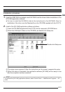
ᕥ [IEEE1394] digital output con-
nector
Digital output connector for video signal.
Used when connecting to the PC’s IEEE
1394 host adapter.
Pin configurations of connectors ( ੬ page
E8)
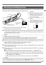
ᕦ [LENS] connector
To connect the lens’ camera cable (for iris
control, power supply).
Pin configurations of connectors ( ੬ page
E9)
Mounting and setting the lens ( ੬ page E15)
LENS
DC IN
POWER
SEE INSTRUCTION MANUAL
REMOTE
IEEE1394
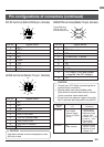
Pin configurations of connectors
Be sure to orientate all plugs correctly before inserting into the respective connectors. If the
direction of insertion is incorrect, the camera may be damaged.
IEEE 1394 connector
2
4
6
1
3
5
Pin no. Signal name
1 VP (Current)
2 VG (GND)
3TPB –
4 TPB +
5TPA –
6TPA +
Part names and their functions (continued)
ᕧ
ᕨ
ᕦ
ᕥ
ᕩ
µ