


16
Introduction
Q
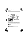
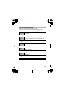
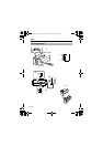
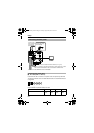
[RX TERM-OFF,ON/INT,LL] Function Selector Switch
ⅷ [RX TERM-OFF,ON] RX Signal Terminal ON/OFF Switch
This sets whether or not the signal between RX+ and RX- from the
control signal connection terminals L should be terminated at the value of
110K resistance.
ON : Terminated at 110K.
OFF : Not terminated at 110K.
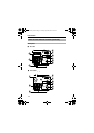
If the system including the camera is the MULTIDROP (Multi DROP, RS-485)
system, only the last camera mounted along the control signal cable is set to
AONB and the other cameras are set to AOFFB. (In the case of the
MULTIDROP system, it is necessary to set the MACHINE ID.)
If the system including the camera is the P TO P (Point to Point, RS-422A)
system, set this switch of all the cameras to AONB. To switch between
communication systems, use the item STYLE on the COMMUNICATION
screen. (A Pg. 51)
(Default setting: ON)
ⅷ [NT,LL] Selector Switch for Synchronizing System
This switch sets the synchronizing system for the camera.
INT : This is set for internal synchronization (INT).
LL (Line Lock) : This is set to synchronize the camera’s vertical
synchronization to the power frequency.
(Default setting: INT)
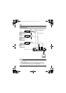
R [POWER] Power indicator lamp
This lamp lights up when power is supplied to the camera.
S Mounting Screw for Fall Prevention Wire
Use this screw when mounting the fall prevention wire to this unit. (Fall
prevention wire is not supplied with this product.)
Note:
● Connect the fall prevention wire to prevent this unit from falling accidentally.
T AC 220 V-240 V power cord
This connects the camera to a commercial AC 220 V-240 V socket.
Name of Parts and their Functions (continued)
C D
TK-C1530_EN.book Page 16 Friday, August 24, 2007 9:29 AM