


23
Note:
● If thin cables are used, the resistance of the cables will be high and a
significant voltage drop will occur when the camera is at its maximum
power consumption. Either use a thick cable with low resistance or place
the power supply near to the camera and shorten the length of the cable to
restrict the voltage drop at the rated current of camera to below 10 %. If
voltage drop occurs during operation, the performance will be unstable.
● Do not connect an AC 24 V cable to a commercial power supply. The
camera will be damaged. If the wrong cable is connected, the internal
circuit may be damaged. Do not use the camera. Bring it to your nearest
JVC dealer for inspection.
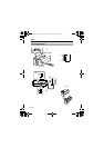
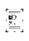
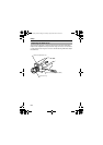
Ⅵ TK-C1531EG (AC 220 V-240 V)
Connect the power supply cable to the AC 220 V-240 V power supply.
Note:
● When you use this camera, the socket - outlet must be installed near the
equipment to make disconnect on easily.
Video signal coaxial cable
Use either RG-59 or RG-11 coaxial cable (BNC).
Do not use other cables.
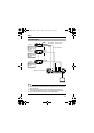
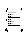
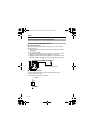
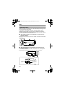
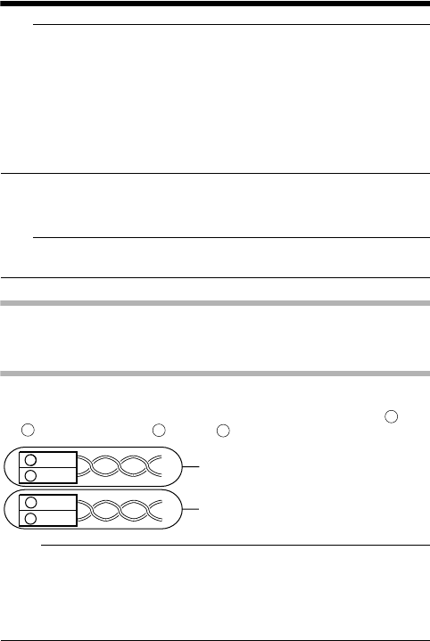
Connecting the control signal cables
Connect the control signal cables in a system where RM-P2580E is used.
As shown in the diagram below, connect the cables such that the TX+ and
TX- signals and the RX+ and RX- signals are in pairs.
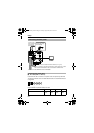
Memo:
● The use of 0.65 mm 4-core (2 pairs) twisted pair cables of impedance
110K is recommended.
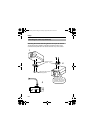
The maximum connection distance with RM-P2580E is 1200 m. For
RM-P2580E, several cameras (up to 16) can be connected to one cable but the
total extension of the cable must be within 1200 m. This is for the case when the
conductor resistance of the cable is below 110
K
and its impedance is 110
K
.
A
B
C
D
A
B
TX+
TX
-
C
D
RX+
RX
-
ˇ
ˇ
Connect in pairs like this.
Connect in pairs like this.
TK-C1530_EN.book Page 23 Friday, August 24, 2007 9:29 AM