


17
Setup
Memo:
● Turn off the power of devices to be used before connecting the cables.
● Read through the “Instruction Manual” of the devices to be used carefully
before connecting.
● For the types of connecting cables and the distances required, read
AConnecting the back panelB (A Pg. 22) carefully before connecting.
● Loop connection cannot be made for control signal cables.
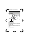
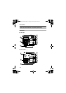
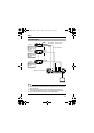
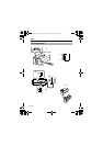
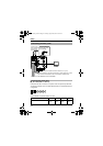
System Example
1
TOCAMERA DATAI/O
RX
+
RX
-
TX
+
TX
-
COM
1 234 567 8
COM
9/110/211/312/413/514/615/716/8
COM COM COM
CAMERA
SW
UNIT
ALARM
AUTO
4312 8756
2 3 4 5 6 7
8
1
MONITOR
OUTPUT
MONITOR
SERIAL-2SERIAL-1
VIDEOINPUT
VIDEOOUTPUT
OUTPUT
2
1
ON
2 3 4 5 6 7
8
DIGITAL
ALC
LEVEL
AvPk
LH
DIGITAL
ALC
LEVEL
AvPk
LH
DIGITAL
ALC
LEVEL
AvPk
LH
Camera 1
Camera 2
Camera 8
Control Signal
Cable
Power
Cable
TK-C1530U/E : AC24 V or DC12 V
TK-C1531EG : AC220 V-240V
Video Signal Cable
Remote control unit and etc
Monitor
MACHINE ID : 1
(MENU screen)
RX TERM : OFF
(Switch)
MACHINE ID : 2
(MENU screen)
RX TERM : OFF
(Switch)
MACHINE ID : 8
(MENU screen)
RX TERM : ON
(Switch)
TK-C1530_EN.book Page 17 Friday, August 24, 2007 9:29 AM