


14
Installation and connection
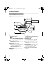
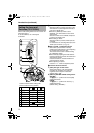
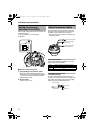
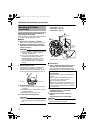
Set the video setting switches on the camera unit
before mounting it.
To set the switches, use a fine-tipped
screwdriver.
A Function selection switches
1. [BLC] Backlight compensation switch.
When the object is placed against the light,
setting this to AONB increases the iris aperture
by 1 stop and the object will appear clearer.
(Default setting: OFF)
2.
Service switch.
Ensure to set to AONB.
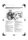
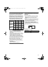
The maximum connection distance varies with
the type of cable used. Please refer carefully to
the table for each cable during connection.
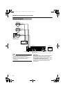
* Be sure to turn off the power of devices before
connecting cables.
Video signal cables
Connect the coaxial cables (BNC) to the video
signal output connector (BNC).
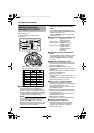
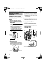
Installing the Ferrite core
(TK-C210FW only)
In order to reduce the influence to the screen
caused by the noise induced from the cable, wind
both Video signal cable and Input power supply
cable once to the supplied Ferrite core.
Setting the Lens and
Switches (TK-C210FW)
BLC
ON
OFF
A
2.
1.
About Connection Cables
Cable Maximum extension (No cable compensator)
RG-59 200 m
RG-6 350 m
RG-11 450 m
To Alarm Signal Cable
(TK-C215V12) Only
To video Signal Cable
To DC 12 V or AC 24 V
Power Supply
Ferrite Core
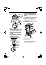
To power supply
To Camera
To video
Signal Cable
TK-S215_EN.book Page 14 Tuesday, March 28, 2006 9:39 AM