


9
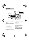
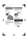
Camera (Interior)
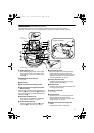
The picture below shows the camera when the dome cover and outer case are removed.
Procedures for removal. (A pg. 18 AEmbedding the camera to the ceilingB, Step 3. to Step 4.)
J Fastening Screw (x 3)
When embedding the camera in the ceiling,
turn this screw to secure the camera. This
screw belongs to a part of the ceiling mount
bracket O.
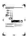
K [MONITOR] terminal (RCA pin)
(A pg. 23)
L Camera Unit
M Fall Prevention Wire Fastening Hook
N Fall Prevention Wire (Supplied) and Wire
Mounting Screw
These are the wires and screws connecting the
camera unit L and the outer case C. One end of
the wire is connected to the fall prevention wire
fastening hook M .
O Ceiling Mount Bracket (x 3)
This is used as a bracket when embedding
the camera to the ceiling. (A pg. 18)
P Camera Fastening Screw
Use this to fasten the camera unit L to the
outer case C. To remove(A pg. 18, 20).
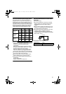
Q Pan fastening Screw
Ensure to loosen the screw before setting.
Further tighten the screw to ensure that
camera's shooting direction does not go out of
alignment only when it is used in a location
with strong vibration. (A pg. 24)
R Imaging Direction mark
Install the camera by aligning the imaging
direction with the arrow mark.
S Rotation Knob
Rotate the lens unit to adjust the inclination of
the image (to be turned).
T Rotation Center Mark
(A pg. 24)
U Tilt Lock screw
Tighten the screw to ensure that camera's
shooting direction does not go out of
alignment when it is used in a location with
strong vibration. (A pg. 24)
V Fall Prevention Wire mounting hole &
Screw
(Fall Prevention Wire not included.)
V
M
N
O
J
L
K
N
P
Q
R
S
T
U
Camera Unit (Rear)
Lens
(A Next page)
*TK-C215V4 is used in the above illustration
TK-S215_EN.book Page 9 Tuesday, March 28, 2006 9:39 AM