


19
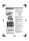
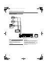
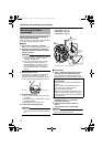
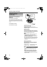
Ⅵ Connecting
1. Attach the fall prevention wire to the
camera, followed by attaching it to the
ceiling slab (Fall prevention wire is not
included.)
2.
Connect the video signal cable. (
A
pg. 14)
Lower the cover and connect the connectors.
Upon connecting, cover the connectors using
the protection cover.
3.
Connect the input power supply cable.
(
A
pg. 15)
4.
Install the Ferrite core (TK-C210FW only)
(
A
pg. 14)
5.
Connect the alarm cable. (TK-C215V12 only)
(
A
pg. 15)
6.
Wrap insulation tape around cables.
7.
Insert the camera unit into the ceiling hole.
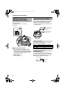
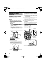
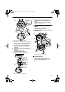
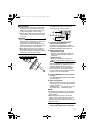
Ⅵ Mounting
1. Align j with the shooting direction when
mounting the camera.
2.
Fasten the camera. (x3 locations)
APress the screw head of the ceiling mount
bracket all the way in using a cross
screwdriver.
BWith the screw pressed in using the
screwdriver, turn about 90 Њ in the
clockwise direction, followed by pulling out
the screwdriver.
CThe ceiling mount bracket is attached to the
ceiling and the camera fastened.
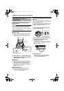
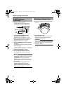
NOTE:
Dismantle the camera upon turning the screw
heads of the ceiling mount bracket (x3) by 90 Њ
in the anti-clockwise direction.
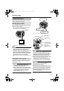
Ⅵ Adjusting Images
After mounting is completed, adjust the
images while checking the actual image.
(A pg. 23 AAdjusting ImagesB)
1.
7.
2.
6.
3.5.
Protection
cover
*TK-C215V12 is used in the above illustration
Alarm signal cable
(TK-C215V12 only)
Solder or crimp
Insulation tape
Wrap with tape
Input power
supply cable
Fall preven-
tion wire
(not supplied)
FRON
T
U
P
B
A
1.
2.
Align with shooting direction
*TK-C215V4 is used in the above illustration
TK-S215_EN.book Page 19 Tuesday, March 28, 2006 9:39 AM