


18
Installation and Connection
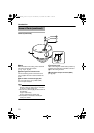
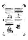
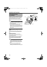
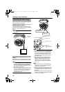
2.Mounting the fall prevention wire to the
base (fall prevention wire is not supplied)
Remove the fastening screw for the fall
prevention wire and mount the fall prevention
wire.
Note:
● Pay attention to the length, strength, routing
and material (insulation properties) of the fall
prevention wire used.
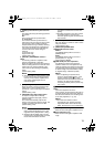
● The internal diameter of the rounded portion
on the camera unit to which the fall
prevention wire is to be mounted shall be at
least R 4.1 mm and not larger than R 6.5 mm,
and its external diameter shall not be larger
than R12 mm.
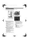
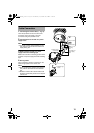
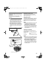
3.Mounting the fall prevention wire to a firm
place
To prevent the camera from falling, mount the
base to a firm place using the fall prevention
wire.
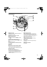
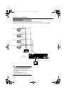
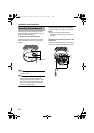
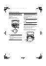
4.Mounting the base
Mount the base by aligning the shooting
direction mark on the inner side of the base (j)
to the shooting direction.
When mounting to the wall, mount it with the
shooting direction mark(j) facing upward.
Do so by using 2 R4 mm mounting screws.
Note:
●
When mounting to the wall, make sure to mount
it with the shooting direction mark (
j
)facing
upward. Failure to do so may cause the fall
prevention wire of the dome cover to come off
easily.
●
R
4 mm screws are not supplied with this
product. Use appropriate type of screw
according to the material of the mounting place.
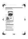
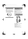
Mounting the base
(continued)
2
4
8mm
2mm
3
Fall Prevention
Wire
Base
R4 mm screw
Align with shooting
direction
(Face upward when
mounting to the wall)
TK-C215VP4_JP.book Page 18 Wednesday, September 20, 2006 5:48 PM