


22
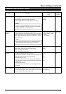
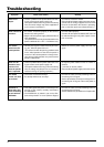
Troubleshooting
Symptom
Video is not
output.
Power cannot be
turned on.
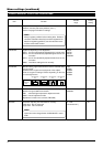
The camera
moves from the
preset position.
Power can be
turned on, but it
later turns off
when the pan/tilt
unit is operated.
The remote
control unit does
not function.
Operation is
abnormally slow
when controlling
the unit with the
RM-P2580.
Cause (Information)
• Is there a problem in the power cables con-nect-
ing the camera to the power supply unit.
(If the power cables are too long or are of the wrong
size, the correct voltage may not be supplied due
to an increase in resistance.)
• Are cables connected properly to the terminal
board on the ceiling mount?
• Was the AC 24 V power supply switched ON and
OFF repeatedly?
(The protection circuit may be activated when the
power is switched ON → OFF → ON within 5 sec.)
• Has the panning been rotated manually for clean-
ing, etc., while the power was on?
(The camera controls the panning position based
on the initial operation at the time the power is
turned on. If the camera position is changed man-
ually after the initial operation. the preset camera
position is displaced.)
• Is there a problem with the power cables con-nect-
ing the camera to the power supply unit.
(If the power cables are too long or are of the wrong
size, the voltage may drop due to an increase in
resistance during the panning operation.)
• Is the cable connected correctly?
• Are the dip switches set correctly?
• Is the cable (particularly the line connecting to TX+
and TX– of the camera) correctly connected to
the RM-P2580?
• The PROTOCOL (2) switch is set on the “Sim-
plex” side by mistake. Is it not? (Refer to Page 6)
Remedy
• Connect low resistance cables.
• Place the AC 24V power supply near to the camera.
(Check that the voltage supplied to the terminal
board is as rated when the camera is operating,
that is, when the rated current flows through it.)
• Connect cables properly.
• Once the AC 24 V power is switched OFF, it should
be switched ON again only after a lapse of more
than 5 seconds.
• Switch the camera power supply OFF then ON
again.
• Change the power cables to ones of a lower re-
sistance
(i.e. thicker or shorter) cables.
• Place the AC 24V power supply near to the camera.
• Connect the cable correctly according to the in-
structions given in Page 9.
• Set the dip switches correctly according to the in-
structions given in Page 6, and turn the power on
again.
• Connect the cable correctly according to the in-
structions given in Page 9.
• Set the PROTOCOL (2) switch to the “Duplex” side.