


9
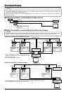
Connections (continued)
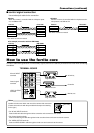
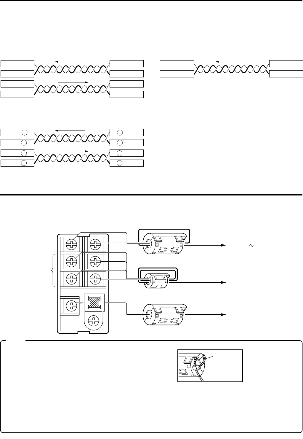
■ control signal connection
Use a twisted-pair cable for the connection.
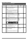
●Duplex
When the camera is controlled with the full duplex proto-
col, set SW5 to OFF.
●Simplex
When the camera is controlled with the simplex transmis-
sion protocol, set SW5 to ON.
Camera Controller
RX+
RX–
TX+
TX–
TX+
TX–
RX+
RX–
Camera Controller
RX+
RX–
TX+
TX–
Two wires must be connected.
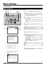
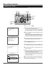
AC 24V
AC 24V INPUT
terminals
Large ferrite core
Small ferrite core
Large ferrite core
TERMINAL BOARD
Control signal
terminals
VIDEO OUTPUT
terminals
Controller
Monitor, etc.
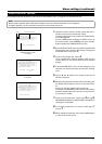
How to use the ferrite core
In order to reduce the generation of unnecessary signals, be sure to install the provided ferrite cores when connecting
the cables.
Install the ferrite cores within 100 mm of the camera-side connectors.
(Fasten the ferrite core with the provided wire clamp as the drawing
on the right.)
• For AC 24V INPUT terminals
Pass the AC 24V cable through the ferrite core twice and cconnect it to the camera.
• For Control signal terminals
Pass the Control signal cable through the ferrite core three times and cconnect it to the camera.
• For VIDEO OUTPUT terminals
Pass the VIDEO SIGNAL cable through the ferrite core and cconnect it to the camera.
Notes
Wire clamp
Four wires must be connected.
●For example (connection with the RM-P2580)
Camera RM-P2580
RX+ C
RX– D
C TX+
D TX–
TX+ A
TX– B
A RX+
B RX–