


4
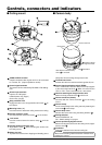
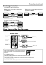
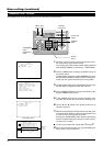
Controls, connectors and indicators
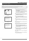
■ Ceiling mount ■ Camera body
View when the camera body
cover is removed
11
15
14
16
15
13
12
Camera position
alignment mark
Dome cover lens
Dome cover
17
Ventilation
18
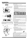
1
VIDEO OUTPUT terminal
Outputs composite video signals and is to be connected
to a monitor, etc. (Output impedance 75ohm)
2
Control signal terminals
The camera can be controlled by RS-422A or RS-485 sig-
nals.
3
AC 24V input terminals
Input the 24 V AC power.
Isolated power only (E type)
Class 2 only (U type)
4
Drop prevention wire
Engage this wire in the drop prevention wire hook
12
on
the camera.
5
Mounting holes (× 4)
Use these holes to attach the ceiling mount to the ceiling.
6
Camera connector (male)
Connects with the camera connector
13
on the camera.
7
Lock screw
Use this screw to fasten the camera clamp
14
to fix the
camera.
8
Camera position alignment mark
Align with the mark
17
when mounting the camera onto
the ceiling mount.
9
Safety wire hole
To prevent the camera from dropping accidentally, pass a
safety wire from the ceiling through these holes.
10
Terminal board cover
Protects the cable connection terminals against dirt, etc.
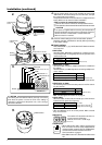
11
Control signal termination switch (TERM)
This is a termination ON/OFF switch for the input signals
to the control signal terminal
2
. When it is set to ON, the
“RX+” to “RX–” route is terminated via 110Ω resistor.
12
Hook for attaching the drop prevention wire
Attach the drop prevention wire
4
to this hook.
13
Camera connector (female)
Connects with the camera connector
6
on the ceiling
mount.
14
Camera clamp
Fix the camera body to the ceiling mount by fastening the
lock screw
7
to this clamp.
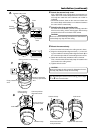
15
Camera body cover
Remove this cover when using the setting switches
16
.
16
Setting switches
Set the PROTOCOL, etc.
Ref. “Switch settings” on page 6.
17
Camera positioning alignment mark
When mounting the camera onto the ceiling mount ,align it
with the mark
8
.
18
Ventilation
This is the ventilator for the internal cooling fan.
23 1
9
(Front)
(Back: Camera side)
4
5
6
5
7
8
10
Make sure that nothing interferes with the ventilator when
installing the camera.
CAUTION