


5
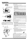
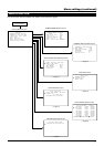
1.
Make a hole (90 mm dia.) in the ceiling for passing through the
connection cables.
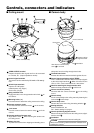
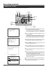
2.
Connect the cables to the terminal board.
Turn the power of all the connected equipment to OFF before
connecting the cables.
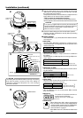
Remove the terminal board cover and connect the video signal
cable (coaxial cable),the control signal cables (× 4) and the AC
24 V power cables (× 2).
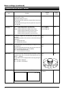
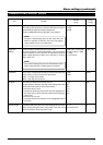
●AC 24 V power cables
Connect the AC 24 V power supply to the AC 24V terminals on
the terminal board. To prevent connection errors or a cable dis-
connection, we recommend the use of lug plates for the connec-
tions.
The following table shows the connection distances and connec-
tion cables provided that 2-conductor VVF cables (vinyl-insulated
vinyl sheath cables) are used.
Installation
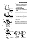
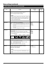
●Control signal cables
These cables should be connected only when it is required to
control the camera using the RS-422A or RS-485 signals. The
use of 0.65 4-conductor twisted pair cables is recommended. With
these cables, the maximum extension distance is 1,200 m.
●Video signal cables
Connect the coaxial cables to the video signal output terminals.
Treat the tips of the coaxial cables as shown on the left before
connection.
After having connected all of the required cables, again attach the
terminal board cover.
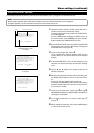
3.
Attach the ceiling mount to the ceiling.
Attach the ceiling mount to the ceiling using 4 screws, while pay-
ing attention not to foul the connection cables.
Use M4 or No. 8-32 UNC screws and bolts for attaching the mount.
If using wood screws, use those with a diameter of 4.1 mm.
The screw head height should be no more
than 4 mm.
• If thin cables are used(i.e. with a high resistance), a significant
voltage drop will occur when the unit is at its maximum power
consumption (pan, tilt, zoom operated simultaneously). Either use
a thick cable to restrict the voltage drop at the camera side to
below 10%, or place the AC 24V power supply near to the camera.
If voltage drop occurs during operation, the performance will be
unstable.
• Attach the cable conductors so that they do not come into con-
tact with the drop prevention wire.
• Be sure to connect the AC 24 V cables correctly. Otherwise the
camera will be damaged.
CAUTION
The ceiling to mount the TK-C675B has to be strong enough to
support ten times the weight of this product.
If the ceiling is not strong enough, make sure to apply reinforce-
ment to the ceiling before installation.
To prevent accidental dropping of the camera, connect the ceiling
plate or channel with the ceiling mount using a safety wire. Thread
the safety wire through the safety wire hole on the ceiling mount.
CAUTION
ø90mm
1.
VIDEO OUT
TX–
RX–
TX+
RX+
Drop prevention wire rail
2.
Remove the terminal board
cover by flipping it up while
pushing its top to the left.
(TX–)(TX+)
(RX–)
(RX+)
6mm
12mm
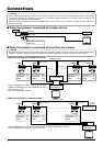
To AC24V
RX+ RX–
To monitor, etc.
TX+
To controller
To controller
Meshed wire
TX–
Polyethylene
Fold the meshed wire back.
Lug plates
Core
conductor
3.
Screws
Ceiling mount
max.
4 mm
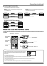
In order to reduce the generation of unnecessary sig-
nals, be sure to install the provided ferrite cores when
connecting the cables.
CAUTION
Maximum extension
100 m 260 m 410 m 500 m
Conductor diameter
1.0ømm
and more than
1.6ømm
and more than
2.0ømm
and more than
2.6ømm
and more than
(reference)