


12
Getting Started
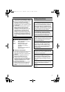
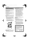
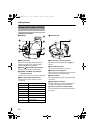
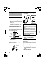
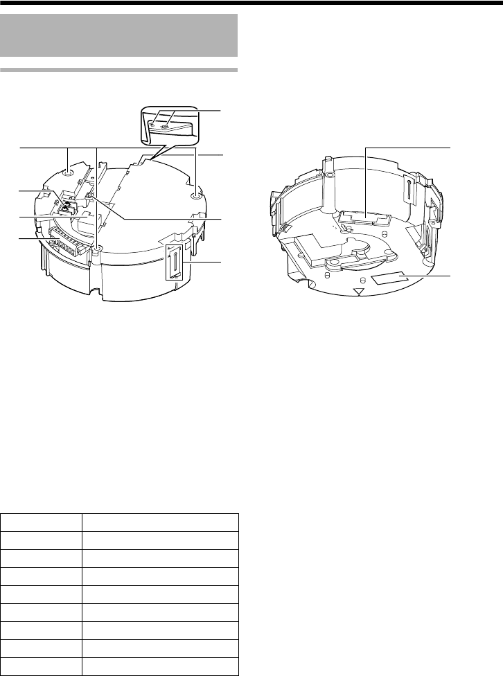
Ceiling mount section
A Fixing holes (x3)
This hole is for mounting the ceiling clamping
bracket to the ceiling or the ceiling recessed
bracket (WB-S685: Sold separately).
B [AC24VHINPUT] AC24V Input terminal
This connects the camera to AC24V power.
C [10BASE-T/100BASE-TX] LAN cable
connection terminal
This connects the unit to the network. (
A
Page 22)
D Alarm input/Alarm output terminal
This terminal is for alarm input/alarm output.
(
A
Page 22)
E Fall prevention wire fixing bracket
This attaches to the fall prevention wire
K
of the
camera.
F Wire clamp fixing hole
This is used to bundle wires. (
A
Page 17)
G Safety wire mounting hole
Mount wires from the ceiling slab or channel to this
hole to prevent the camera from falling.
H Power indicator
The indicator lights up in green when AC24V power
is turned on.
I [Mac address] indication
The MAC address is a unique physical address of
the product. This address cannot be altered.
J Camera connection terminal (female)
This connects to the connection terminal (male) of
the camera.
Name and Function of Parts
B
D
C
F
E
G
A
H
Ⅵ
Terminal
J
I
Ⅵ Reverse side
Pin number Signal Name
1 Input 1
2 Input 1 COM
3 Input 2
4 Input 2 COM
5 Output 1
6 Output 1 COM
7 Output 2
8 Output 2 COM
VN-V686WPU_EN.book Page 12 Wednesday, January 16, 2008 10:39 AM