


16
Connection/Installation
Preparation
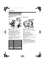
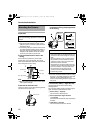
1 Make holes on the ceiling
● Use the provided template to make a hole
(R80 mm) for the connection cables to thread
behind the ceiling.
● If necessary, also open a screw hole to mount
the ceiling clamping bracket to the ceiling. In
this case, align the AD FRONT markB of the
template in the direction where the camera
faces front and open the screw hole.
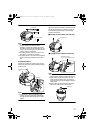
2 Pull the cables from the hole in the
ceiling
Pull out the fall prevention wire, power cable,
coaxial cable, control signal cable, alarm signal
cable and provided alarm cable that were mounted
to the ceiling slab from the ceiling.
Note:
● Mount the fall prevention wire on a firm place
with sufficient strength.
3 Remove the terminal cover
Loosen two screws on the ceiling clamping bracket
and remove the terminal cover.
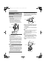
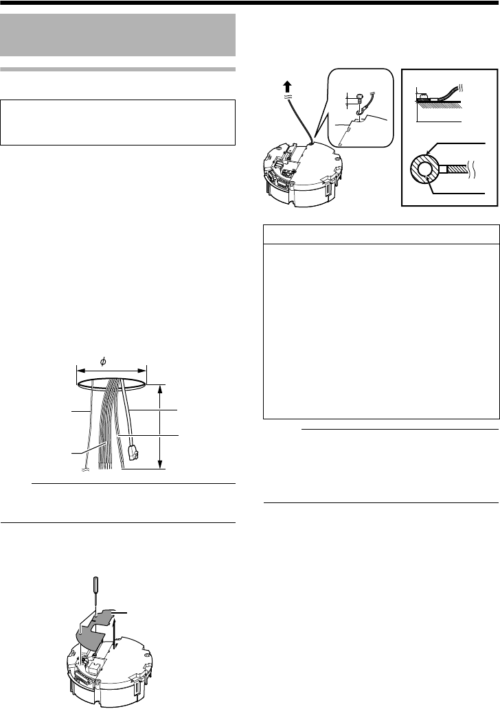
4 Mount the fall prevention wire that
connects the ceiling clamping bracket
to the ceiling
M
emo:
● The wire should be insulated from the ceiling
structure. If the ceiling structure is metal and
insulation is not provided between the
camera and the ceiling structure, image noise
may occur.
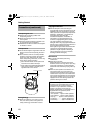
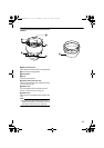
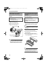
5 Connect the cable (A Page 20 to 23)
Connect cables to the terminal of the ceiling
clamping bracket.
The connection cables consist of the alarm signal
cable, LAN cable and AC24V power cable.
A Power cable (A Page 20)
This connects to AC24V power.
B Alarm input/output signal terminal
(A Page 22)
This connects to devices with alarm input/output
terminals.
C LAN cable (A Page 22)
This connects the unit to the network.
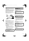
Mounting the Camera
Be sure to put on protective glasses to protect
your eyes from falling objects when mounting the
camera.
1
80
2
A
larm signal cable
Power cable
LAN Cable
Fall Prevention
Wire
Terminal cover
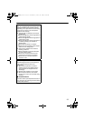
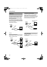
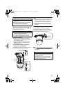
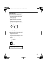
Caution
●
Take note of the length, strength, pull and
material (insulation) of the fall prevention wire
and use one with a wire strength of more than
20k
g
.
●
The inner diameter of the ring section of the
fall prevention wire mounted on the camera
should be
R
4 mm to
R
5.5 mm and the outer
diameter be
R
9 mm and below.
●
The thickness of the screw head and the fall
prevention wire (including the washer) should
be 6 mm and below. If it is more than 6 mm,
the screw will touch the ceiling and the
camera cannot be installed horizontally.
●
Use M4 fixing screws.
6 mm
(15/64 inch)
Ⅵ
Fall Prevention Wire
6 mm and below
R6 mm and below
R4 to 5.5 mm
VN-V686WPU_EN.book Page 16 Wednesday, January 16, 2008 10:39 AM