


17
Note:
● Do not connect an AC 24 V cable to AC 100
V power supply. The camera will be
damaged. If the wrong cable is connected,
the internal circuit may be damaged. Do not
use the camera. Bring it to your nearest JVC
service center for inspection.
● For safety reasons, turn on the power only
after all the connection is complete.
● To supply AC 24 V, use a AC 24 V supplying
power unit that is insulated from AC 100 V
line.
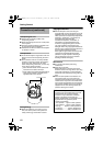
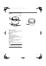
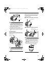
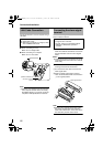
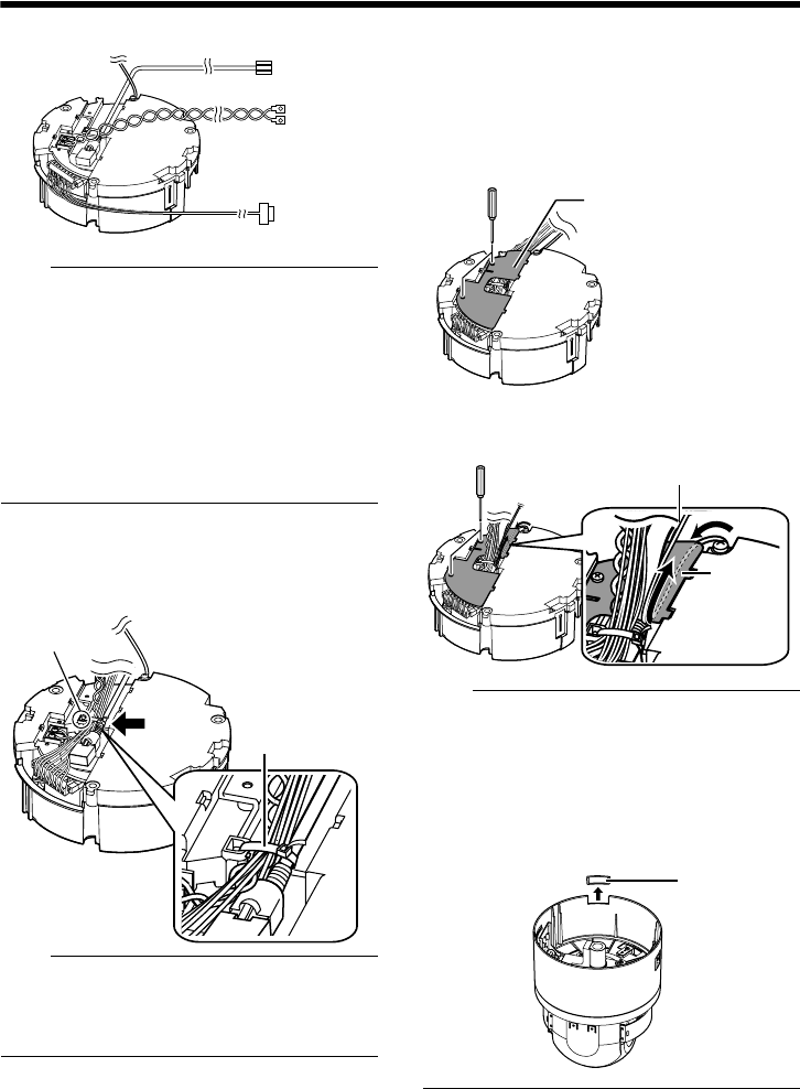
6 Handling cables
Thread the provided wire clamp through the wire
clamp fixing hole of the ceiling clamping bracket to
tie all the wires.
Tie here
Wire clamp fixing
hole
Wire clamp
Note:
● To prevent the cables from tangling and
coming off, be sure to thread a wire clamp
through the wire clamp fixing hole to tie the
cables.
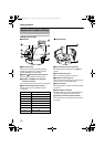
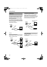
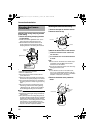
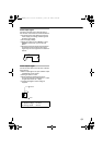
7 Mount the terminal cover
Return the terminal cover that was removed in step
3
to its original position. The direction to pull out
the cables changes according to the mounting
method of the camera.
Note:
● Be sure to mount the terminal cover to
prevent foreign objects or dust from entering.
● When pulling out the cables from the top,
make the fall prevention wire go under the
terminal cover and pull it out together with the
other cables.
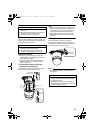
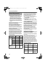
● When pulling out the cables from the side,
remove the cable cover of the camera.
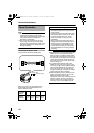
A
B
C
Alarm signal cable
Power cable
LAN Cable
Ⅵ Pulling out the cables from the top
Terminal cover
Fall Prevention Wire
(To go under the terminal cover)
Ⅵ Pulling out the cables from the side
Te r mi n al
cover
Cable cover
VN-V686WPU_EN.book Page 17 Wednesday, January 16, 2008 10:39 AM