


GE1900 User Manual
70-0028A-A
Prosilica Inc.
6
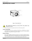
Item 1: GIGABIT ETHERNET PORT
This port conforms to the IEEE 802.3 1000BASE-T standard for Gigabit Ethernet over copper.
It is recommended that CAT5E or CAT6 compatible cabling and connectors be used for best
performance. Cable lengths up to 100m are supported.
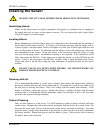
Item 2: General Purpose I/O PORT
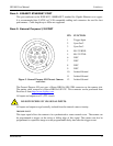
PIN FUNCTION
1 Trigger Input
2 Sync Out 2
3 Sync Out 3
4 RS-232 RXD
5 RS-232 TXD
6 DNC
7 DNC
8 DNC
9 DNC
10 Isolated Ground
1
2
3
4
5
6
7
8
9
10
11
12
11 Isolated Ground
Figure 3. General Purpose I/O Pin out. Camera
rear view.
12 Isolated Ground
The General Purpose I/O port uses a Hirose HR10A-10R-12SB connector on the camera side.
The mating cable connector is Hirose HR10A-10P-12P. This connector can be purchased from
Prosilica or from http://www.digikey.com.
All inputs and outputs are 5V (TTL) levels.
DO NOT EXCEED 5.5V ON SIGNAL INPUTS.
All inputs and outputs are galvanically isolated from the internal camera circuitry.
TRIGGER INPUT
This input signal allows the camera to be synchronized to some external event. The camera can
be programmed to trigger on the rising or falling edge of this signal. The camera can also be
programmed to capture an image at some programmable delay time after the trigger event.