


GE1900 User Manual
70-0028A-A
Prosilica Inc.
7
Sync Out 2 and Sync Out 3
These signals only function as outputs and can be configured as follows:
Exposing Corresponds to when camera is
integrating light.
Trigger Ready Indicates when the camera will accept a
trigger signal.
Trigger Input A relay of the trigger input signal used
to “daisy chain” the trigger signal for
multiple cameras.
Readout Valid when camera is reading out data.
Strobe Programmable pulse based on one of the
above events.
Imaging Valid when camera is exposing or
reading out.
GPO User programmable binary output.
Any of the above signals can be set for active high or active low.
RS-232 RXD and RS-232 TXD
These signals are RS-232 compatible. These signals allow communication from the host system
via the Ethernet port to a peripheral device connected to the camera.
ISOLATED GROUND
These signals are internally connected to isolated ground. At least one of these signals must be
connected to the users external circuit ground. However, it is good practice to provide a
dedicated ground return for each signal used. For example, a good cable design would connect
the required signal on one conductor of a twisted pair and the isolated ground on the second
conductor of the same twisted pair.
DNC
These signals are reserved for future use and should be left disconnected.
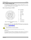
Item 3: Mini-SMB Trigger Input
The Mini-SMB port on the camera uses an Amphenol 903-406J-51R connector. A suitable
mating cable connector is Amp 413985-3 which can be used with RG174 coaxial cable. Contact
Prosilica to purchase cabling.
The Mini-SMB Trigger Input is internally connected to the Trigger Input (Pin 1) of the General
Purpose I/O Port (Item 2 above). Therefore see this section for more detail.