


Chapter 3 Making Grayscale and Color Measurements
© National Instruments Corporation 3-5 IMAQ Vision for Visual Basic User Manual
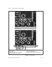
During design time, use the Menu property page to select which tools
appear in the right-click menu. You also can designate a default tool from
this property page. During run time, set the
CWIMAQViewer.MenuItems
to select the tools to display, and set
CWIMAQViewer.Tool to select the
default tool.
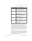
Defining Regions Programmatically
You can define ROIs programmatically using the CWIMAQRegions
collection. In IMAQ Vision, shapes are represented by shape objects.
For example, CWIMAQPoint represents a point, and CWIMAQLine
represents a line. Use the following methods listed in Table 3-2 to add
various shapes to the regions.
Use the
CWIMAQRegions.CopyTo method to copy all the data from one
CWIMAQRegions object to another.
You can define the regions on a viewer and access the regions using the
CWIMAQViewer.Regions property.
The individual CWIMAQRegion objects provide access to the shapes in the
collection. Each region has one shape object associated with it. Use the
CWIMAQRegion.Shape property to determine what type of shape the
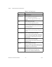
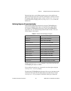
Table 3-2. Methods that Add Shapes to Regions
Method Description
AddPoint adds a point to the ROI
AddLine adds a line to the ROI
AddRectangle adds a rectangle to the ROI
AddRotatedRectangle adds a rotated rectangle to the ROI
AddOval adds an oval to the ROI
AddAnnulus adds an annulus to the ROI
AddBrokenLine adds a broken line to the ROI
AddPolygon adds a polygon to the ROI
AddFreeline adds a free line to the ROI
AddFreeregion adds a free region to the ROI
AddRegion adds a region object to the ROI