


Chapter 6 Calibrating Images
IMAQ Vision for Visual Basic User Manual 6-4 ni.com
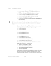
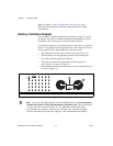
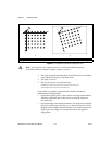
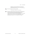
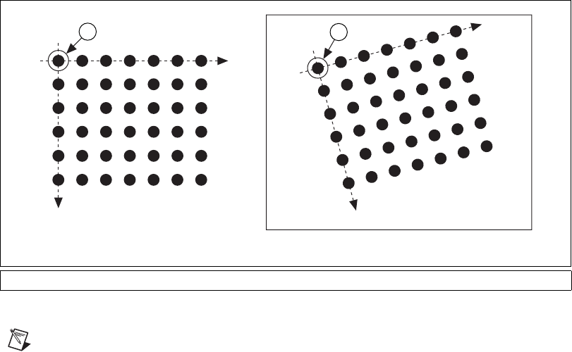
Figure 6-3. A Calibration Grid and an Image of the Grid
Note
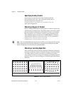
If you specify a list of points instead of a grid for the calibration process,
the software defines a default coordinate system, as follows:
1. The origin is placed at the point in the list with the lowest x-coordinate
value and then the lowest y-coordinate value.
2. The angle is set to 0°.
3. The axis direction is set to indirect using
CWIMAQCoordinateSystem.AxisOrientation=
cwimaqAxisOrientationIndirect
.
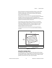
If you define a coordinate system yourself, carefully consider the
requirements of the application:
• Express the origin in pixels. Always choose an origin location that lies
within the calibration grid so that you can convert the location to
real-world units.
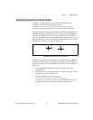
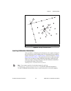
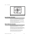
• Specify the angle as the angle between the x-axis of the new coordinate
system (x') and the top row of dots (x), as shown in Figure 6-4. If the
imaging system exhibits nonlinear distortion, you cannot visualize the
angle as you can in Figure 6-4 because the dots do not appear in
straight lines.
1 Origin of a Calibration Grid in the Real World 2 Origin of the Same Calibration Grid in an Image
y
x
a.
y
x
b.
1
2