


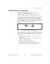
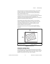
Chapter 6 Calibrating Images
IMAQ Vision for Visual Basic User Manual 6-2 ni.com
Refer to Chapter 5, Performing Machine Vision Tasks, for more
information about applying calibration information before making
measurements.
Defining a Calibration Template
You can define a calibration template by supplying an image of a grid or
providing a list of pixel coordinates and their corresponding real-world
coordinates. This section discusses the grid method in detail.
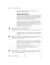
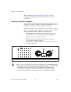
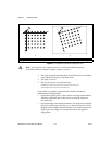
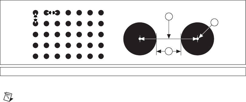
A calibration template is a user-defined grid of circular dots. As shown in
Figure 6-1, the grid has constant spacings in the x and y directions. You can
use any grid, but follow these guidelines for the best results:
• The displacement in the x and y directions must equal (dx = dy).
• The dots must cover the appropriate portion of the working area.
• The radius of the dots must be 6–10 pixels.
• The center-to-center distance between dots must range from
18 to 32 pixels, as shown in Figure 6-1.
• The minimum distance between the edges of the dots must be 6 pixels,
as shown in Figure 6-1.
Figure 6-1. Defining a Calibration Grid
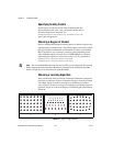
Note
You can use the calibration grid installed with IMAQ Vision at Start»Programs»
National Instruments»Vision»Documentation»Calibration Grid. The dots have radii
of 2 mm and center-to-center distances of 1 cm. Depending on the printer, these
measurements may change by a fraction of a millimeter. You can purchase highly
accurate calibration grids from optics suppliers, such as Edmund Industrial Optics.
1 Center-to-Center Distance 2 Center of Grid Dots 3 Distance Between Dot Edges
dy
dx
1
3
2