


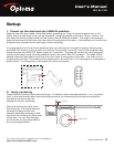
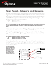
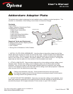

Rear Panel View
+9V DC In
+12V Trigger Out
+12V Trigger In
Remote IR Sensor In
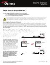
To screen
masking system
From projector
or scaler
User’s Manual
BX-AL133
For more information, please visit our website at:
http://www.OptomaUSA.com
User’s Manual | 11
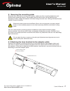
Rear Panel − Triggers and Sensors
To use the automatic lens trigger, your projector or scalar must be equipped with a lens
trigger and a standard double-ended 3.5 mm (1/8 inch) male mono or stereo jack cable.
Simply plug the cable into the projector’s lens trigger jack and into the sled +12V Trigger-
In jack. Follow the projector or scalar instructions to configure the lens trigger.
The Trigger-In (tip positive) operates as follows:
+12V LENS IN command
0V LENS OUT command
NOTE: The input trigger jack may be temporarily overridden by the remote control. When
the next transition of voltage occurs (up or down), the trigger will take control once
again.
Another option allows you to use the +12V Trigger-Out jack on the rear of the device. The
output jack is set to +12V whenever the sled is in the LENS OUT position.
This is typically used for triggering screen masking systems to mask the side of the
screen when an HDTV (16:9) image is being projected instead of a widescreen (2.35:1)
DVD movie format.
The Trigger-Out jack (tip positive) operates as follows:
0V Lens is in the LENS IN position
+12V Lens is in the LENS OUT position
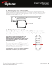
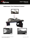
Each sled is supplied with an optional remote IR sensor which may be used to improve
reception if the sled is located where IR signals cannot be reached. It may also be used
with an IR repeater system by simply taping the remote sensor to one of the IR emitters
from the repeater system.
To use, simply peel
off the included self-
stick tape, affix to a
convenient location
and plug the 2.5
mm cable into the
appropriate jack in
the back of the unit.