


User’s Manual
BX-AL133
For more information, please visit our website at:
http://www.OptomaUSA.com
User’s Manual | 17
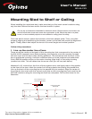
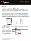
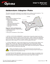
4. INSTALL CHAINS. Hold the chain to the ceiling so that one end of the chain hangs
just above one of the installed plate hooks. Mark the ceiling location and repeat for the
other chain hook. Procure and install the ceiling hooks at those locations small enough
to accept a chain end, and strong enough when installed to support approximately 40
pounds (or more). The type of hook and method of installation may depend on the type
of ceiling you have. Cut the chain to make chain segments. The ones that come closest
to supporting the lens plate when attached to the chain ends should be the ones that
are attached to the plate and ceiling hooks. Install the lens chains and adjust the nuts
on the plate hooks to make the chains tight, but without raising the front of the plate.
Tighten the plate hook nuts to compress the lock washer in the plate hook assembly.
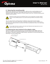
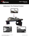
5. MOUNT THE ANAMORPHIC LENS.
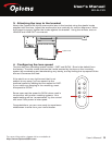
INSTALLATION WITHOUT THE MOTORIZED MOUNT:
a. Remove the lens from its lens bracket.
b. Orient the lens bracket to the lens plate so that the angled sides of the lens
bracket are toward the back of the plate. Install the four lens mount assemblies
(large assemblies with white spacers) from the top down through the four holes
that are for the lens in the order of screw, flat washer, lens plate, white spacer,
lens bracket, flat washer, lock washer and nut. Use the hex key to tighten the
nuts so that the lens mount assemblies are centered in the elongated lens bracket
holes.
c. Turn the projector on and project a full, yet still 16:9 image from the projector.
Carefully install the lens and adjust the tilt to equalize the top and bottom image
geometry while positioning the lens vertically to center the output beam. Tighten
the lens knobs.
INSTALLATION WITH MOTORIZED MOUNT:
a. Do Not Connect the Power of the Motorized Mount at this Time.
b. Position the motorized mount on the bottom side of the lens plate so that the six
holes (refer to the diagram on the previous page) in the lens plate line up with
the six holes in the flat side of the motorized mount. Insert the four small 1/4”
screws through the four small holes of the lens plate into the motorized mount and
tighten.
c. Insert the sled safety assemblies through the remaining two holes from bottom up
in the order of screw, motorized mount, lens plate, washer, lock washer and nut.
Tighten both safety assemblies.
d. Refer to the motorized mount user manual for additional instructions at this time.
Use extreme caution and appropriate hardware when installing heavy objects to a
ceiling. Periodically check all fasteners and connection hardware to be sure they have
not come loose. Improper installation may lead to an increased risk of your equipment
becoming unstable and possibly causing injures.