


34
Menu contents
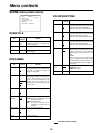
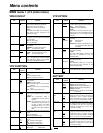
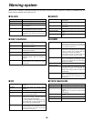
MAIN menu 1 of 2 (main menu)
VIDEO IN/OUT
Item
Setting
options
Remarks
VIDEO OUT MENU ON
OFF
For selecting whether to output the menu
screens to the VIDEO OUT connector.
ON: For the screens are output.
OFF:For the screens are not output.
<Note>
The VIDEO OUT MENU item is valid only
when ENC has been selected as the
VIDEO OUT setting.
SET UP 0%
7.5%
For selecting the CAM OUT/VIDEO OUT output
setup. For selecting the CAM OUT/VIDEO
OUT output setup. When 7.5% is selected,
7.5% setup is also applied to the tape.
VIDEO OUT SEL ENC
VF
For selecting whether the VTR signals or
VF signals are to be output from the VIDEO
OUT connector.
ENC:For VTR output
VG: For VF output
INPUT SELECT CAMERA
1394
For selecting the input signals of the VTR to
be recorded.
CAMERA: For unit’s camera signals
1394: For signals from 1394
REMOTE SELECT LOCAL
1394
For selecting the VTR control.
LOCAL: For control from the unit only
1394: For control from 1394
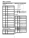
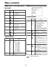
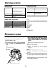
VTR FUNCTION
Item
Setting
options
Remarks
TC MODE DF
NDF
For setting the time code to the DF or NDF
mode.
DF: For drop frame mode
NDF:For non-drop frame mode
FF/REW SPEED
a32
a64
a
100
For setting the fast forward and rewind
speed.
a
32: 32 times normal speed
a
64: 64 times normal speed
a
100:100 times normal speed
AUDIO SAMPLING 32K
48K
For selecting the audio sampling frequency.
32K: 32 kHz 48K: 48 kHz
UB MODE USER
TIME
DATE
TCG
For selecting what is to be recorded in the
user’s bit area.
USER:User setting (fixed)
TIME: Real time value in hours/minutes/
seconds
DATE:Real time value in year/month/day/
hours
TCG: Time code generator value
FIRST REC TC REGEN
PRESET
For selecting whether the TC REGEN
mode is to be established when recording
is started.
REGEN: The regeneration mode is
established for the time code on
the tape.
PRESET:The regeneration mode is not
established for the time code on
the tape. However, it is forcibly
established when the unit is
transferred from REC PAUSE to
REC.
BACK TALLY ON
OFF
For selecting whether the back tally lamp is
to light.
ON: The lamp lights.
OFF:The lamp does not light.
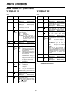
VTR OPTION
Item
Setting
options
Remarks
TIME STAMP REC
NO-REC
For selecting whether to superimpose the date
and time onto the camera’s video recording.
REC: For superimposed
NO-REC:For not superimposed
<Note>
When REC is selected, select the type of
date and time to be superimposed with the
TIME/DATE item of <VF DISPLAY 2/2>
sub-menu.
PAUSE TIME 3min
6min
10min
For setting the time that is allowed to elapse
before REC PAUSE is replaced with SAVE.
INTERVAL REC OFF
ON
ONE-SHOT
For setting whether to perform intermittent
recording.
OFF: Not performed
ON: Performed
ONE-SHOT:
Recording is performed once for
the period set for REC TIME, and
then stops.
INTERVAL TIME 00h00m10s
:
23h59m59s
For setting the REC PAUSE time during
intermittent recording.
<Note>
The INTERVAL TIME item is valid only
when ON has been selected as the
INTERVAL REC setting.
REC TIME 00m05s
:
59m59s
For setting the recording time for
intermittent recording.
<Note>
The REC TIME setting is effective only
when ON or ONE-SHOT is set for
INTERVAL REC.
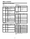
BATTERY
Item
Setting
options
Remarks
BATTERY SELECT NiCd12
NiCd13
NiCd14
TYPE A
TYPE B
For selecting the type of battery used.
NiCd12: NP-1B made by Sony
NiCd13: TRIM13 made by Anton Bauer
NiCd14: TRIM14 made by Anton Bauer
TYPE A:AJ-BP490
TYPE B:Digital 14 V (Hitron 100) made by
Anton Bauer
TYPE B END 11.0V
:
12.5V
:
15.0V
For designating the type B voltage. When
the voltage set here is reached, the battery
is considered to be flat, and a warning is
displayed. A voltage from 11.0 V to 15.0 V
is used as the setting.
TYPE A NEAR
END
11.0V
:
11.6V
:
15.0V
For designating the type A voltage. When the
voltage set here is reached, the battery is
considered to have a minimal remaining
charge, and a warning is displayed. A voltage
from 11.0 V to 15.0 V is used as the setting.
TYPE B NEAR
END
11.0V
:
13.0V
:
15.0V
For designating the type B voltage. When the
voltage set here is reached, the battery is
considered to have a minimal remaining
charge, and a warning is displayed. A voltage
from 11.0 V to 15.0 V is used as the setting.
TYPE A END 11.0V
:
11.2V
:
15.0V
For designating the type A voltage. When
the voltage set here is reached, the battery
is considered to be flat, and a warning is
displayed. A voltage from 11.0 V to 15.0 V
is used as the setting.
“ ” indicates the factory setting.