


7
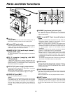
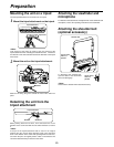
Parts and their functions
B
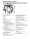
MENU button
This is used to switch the menu ON and OFF.
A
JOG dial button
This is used to select the menu items and perform settings when
the MENU button B is at the ON position. When the synchro
scanning mode has been selected for the shutter speed, the
shutter speed can be easily adjusted more finely.
?
FULL AUTO button
This is pressed when there is no time to check the camera unit’s
settings. The lens iris and white balance will be automatically
adjusted.
@
FULL AUTO lamp
This lights up when FULL AUTO shooting is being performed.
>
AUTO IRIS MODE selector switch
This is used to select the position that matches the shooting
conditions when shooting by automatically adjusting the lens
iris.
BACK.L : When making a back-lit subject brighter for shooting
STD : For normal shooting
SPOT.L : For shooting a spot-lit subject
=
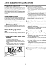
QUICK FOCUS button
This supports the focusing of the subject. When it is pressed,
the lens iris is opened for about 10 seconds. It makes the depth
of field shallower and facilitates focusing.
<
MODE CHECK button
This enables the setting modes of the camera’s control switches
to be checked in the viewfinder.
;
SCENE FILE dial
This enables the camera settings that match the shooting
conditions to be selected. For further details, refer to “How to
use file select” (page 24).
:
SPEAKER
The sound can be monitored through this speaker.
When an earphone is connected to the PHONE jack, the sound
of the speaker will be automatically cut off.
What can be monitored is the mixed sound of CH1 and CH2.
7
MONITOR (volume) control
This is used to adjust the volume of the monitor speaker or
earphone.
8
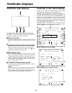
AUDIO LEVEL CH1, CH2 (audio channel 1,
2 recording level) controls
These are used to adjust the CH1 and CH2 recording levels
while monitoring the level meter inside the viewfinder.
9
POWER/WARNING lamp
This lamp lights up green when the power is turned on, and it
flashes in green during interval recording. When a warning is
given, it lights up red or flashes in red to alert the user. For
further details, refer to “Warning system” (page 38).
6
BREAKER switch
If an excessively high current flows inside the unit due to some
problem or other, the circuit breaker is tripped and the power is
automatically turned off to protect the unit.
Push this button in after conducting an inspection or repairs
inside the unit. If there are no problems, the power will come
back on.
D
COUNTER selector switch
This is used to switch the counter display.
COUNTER: A relative numerical value is displayed by the
counter. However, when the tape recording
includes discontinuous parts, the counter reading
may also lack continuity.
TC : The time code is displayed.
UB : The user’s bit is displayed.
E
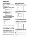
TCG selector switch
This sets the time code operation mode to FREE RUN, REC
RUN or SET. For further details, refer to “Setting the time data”
(page 22).
F
AUDIO SELECT CH1, CH2 (audio channel 1,
2 auto/manual level adjustment selector)
switches