


40
Maintenance
When the unit is taken from cold to warm surroundings or
used in a very humid place, the water vapor contained in the
air may turn into droplets of water when it makes contact
with the head drum. This phenomenon is known as
condensation, and if the tape is run while condensation has
formed inside the unit, the tape tends to stick to the head
drum.
Bear in mind the following points:
≥Remove the tape before starting to use the unit under
conditions which may be conducive to the formation of
condensation.
≥Before inserting the tape, set the power switch to ON, and
check that the HUMID display has not lighted in the
viewfinder.
<Note>
To ensure safety, the HUMID display remains flashing and
the head drum is rotated for 80 minutes after the
condensation detection has been released.
During this period, none of the control buttons will operate.
Condensation
Use the AY-DVCL cleaning cassette as necessary to clean
the heads.
Since the video heads may be damaged if the proper
directions for using cleaning cassette are not followed, read
the handling instructions which accompany the cleaning
tape prior to use.
Cleaning the heads
≥Do not use paint thinners or other solvents to remove dirt.
≥Use any of the lens cleaners available on the market to
wipe the lens.
≥Never wipe the mirror under any circumstances.
If dirt or dust has adhered to the mirror, blow it away using
an air blower available on the market.
Cleaning inside the viewfinder
Smear
This may occur when extremely bright subjects are shot.
The higher the electronic shutter speed, the more this
phenomenon is liable to occur.
Phenomena inherent to CCD
cameras
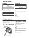
Replacing the backup battery
The backup battery is mounted in the unit prior to the unit’s
shipment from the plant.
When the backup battery is used up and the power switch is
set to ON, the BACKUP BATTERY EMPTY message
appears in the viewfinder for 5 seconds.
Consult your dealer before replacing the old backup battery
with a new one (CR2032). After replacing the battery, press
the backup battery cover firmly into place until a click is
heard. For details on the battery position, refer to “Parts
and their functions” (pages 6 and 7).
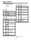
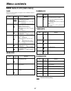
Error codes
When an error has occurred in the unit for some reason or other,
one of the error codes shown on the right will be displayed in the
viewfinder.
Code No.
Description
04 Problem with the pinch solenoid or reel brake
solenoid
08 Problem with the cleaning solenoid
0B Problem with the supply reel
0C Problem with the take-up reel
0D Problem with the capstan
0E Problem with the head cylinder
0F Problem with loading
3F Problem with the servo reference signal